VertiGIS FM can display doors/gates and windows in your floor plan drawings provided the attributes are defined in the CAD Administration and CAD Configuration. You must also create symbols to determine how you want the doors and windows to appear on the drawing.
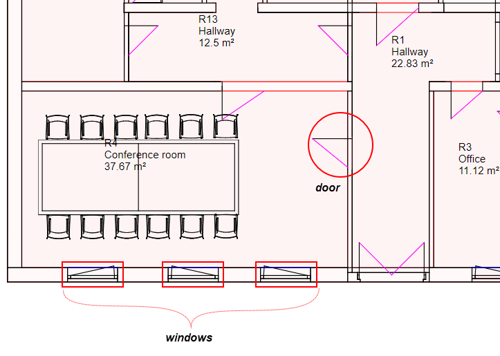
Doors and Windows Indicated by Symbols on Floor Plan Drawing
If your DXF file contains attributes for doors and windows, you must ensure the prerequisites below are set in order for them to display properly. These prerequisites must be met before you import the DXF file into VertiGIS FM.
Ensure Door and Window Attributes Are Present in CAD Administration
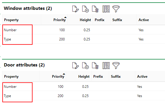
The Window Attributes and Door Attributes sections on the CAD Administration page (Administration > Settings > CAD Administration) must both contain entries for the Type and Number attributes.
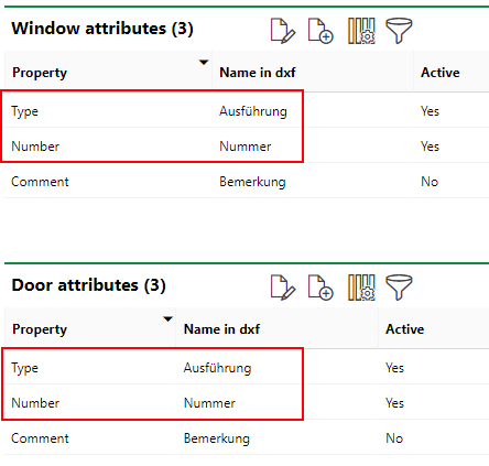
Door and Window Attributes Sections on the CAD Administration Page
The names in the Name in DXF column must match the attribute names used in your CAD drawing.
Add or Edit Door or Window Attributes
You can add a new attribute by clicking the Add (![]() ) icon. You can edit, activate, or deactivate an attribute by selecting it and clicking the Edit (
) icon. You can edit, activate, or deactivate an attribute by selecting it and clicking the Edit (![]() ) icon.
) icon.
Ensure Door and Window Attributes Are Present in CAD Configuration
The attributes created on the CAD Administration page must also be present in the CAD Configuration.
To Add Door and Window Attributes to CAD Configuration
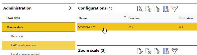
1.Navigate to the CAD Configuration page (Administration > Master Data > CAD Configuration).
2.Double-click the configuration being used. If no configuration is present, create one.
3.Expand the Window Attributes section and click the Add (![]() ) icon.
) icon.
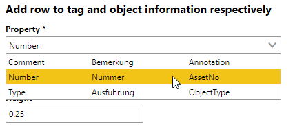
4.From the Property drop-down menu, select the Number attribute stored in the CAD Administration.
5.Enter a Priority for the attribute and fill out the optional form fields as applicable.
6.Click Save and Close.
7.In the Window Attributes section, click the Add (![]() ) icon.
) icon.
8.From the Property drop-down menu, select the Type attribute stored in the CAD Administration.
9.Enter a Priority for the attribute and fill out the optional form fields as applicable.
10.Click Save and Close.
11.Expand the Door Attributes section and repeat steps 3-10 so that the Number and Type attributes are both present.
Configure CAD Settings for Doors and Windows During Import
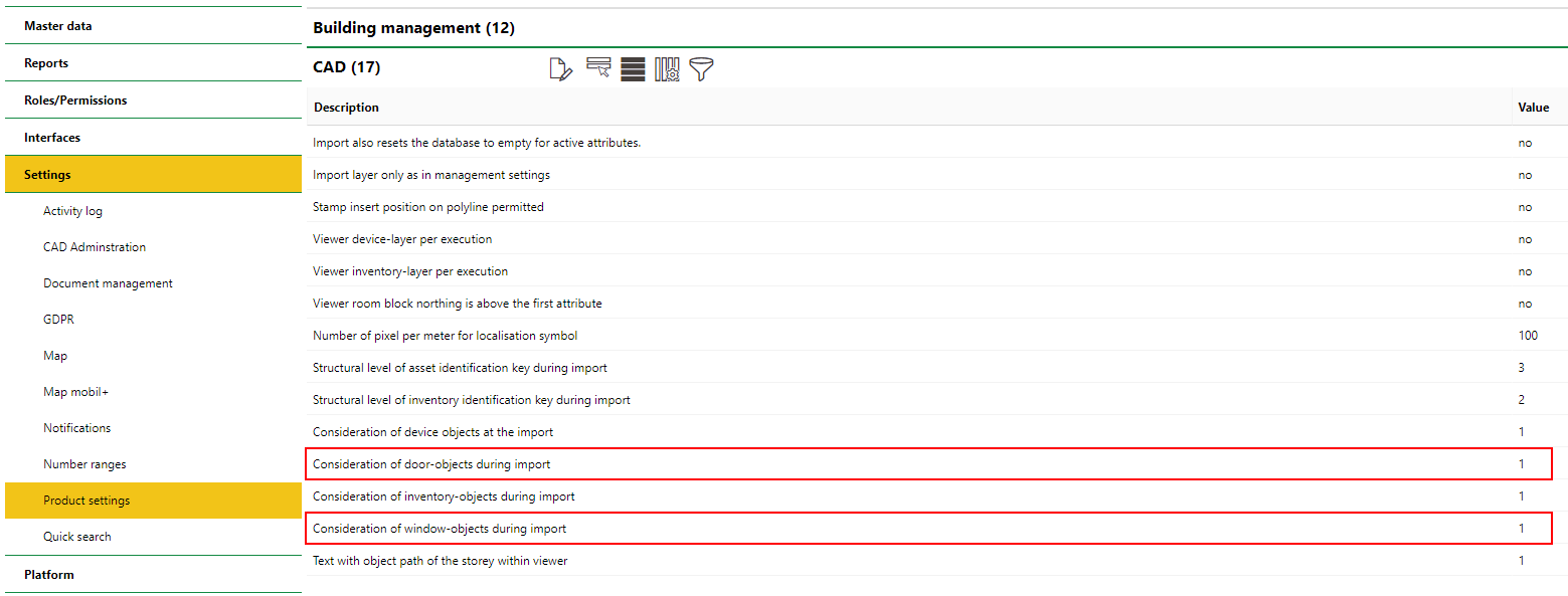
To import a floor plan drawing that represents doors and windows, you must configure the settings below as noted on the Administration > Settings > Product Settings page. Refer to CAD Settings for more information.
Setting |
Value |
|---|---|
Consideration of door-objects during import |
1 |
Consideration of window-objects during import |
1 |
To Configure CAD Settings for Door and Window Import
1.Navigate to the Product Settings page (Administration > Settings > Product Settings).
2.Expand the CAD Settings section.
3.Select the Consideration of door-objects during import setting and click the Edit (![]() ) icon.
) icon.
4.In the Value box, enter 1 and then click Save and Close.
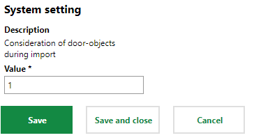
5.Select the Consideration of window-objects during import setting and click the Edit (![]() ) icon.
) icon.
6.In the Value box, enter 1 and then click Save and Close.
CAD Settings to Import Drawing with Doors and Windows
Create Symbols for Doors and Windows
You must create symbols for the images you want to represent the doors and windows on the CAD drawing and then assign them to the doors and windows in VertiGIS FM.
Refer to Create a Symbol for instructions on how to create a symbol. After you create the symbol, edit it and select the Window or Door/Gate check boxes depending on the type of object the symbol will represent.
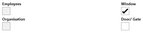
Edit Symbol Form
When the prerequisites above are satisfied, you can import a CAD drawing with door and window attributes, and the doors and windows will display using the corresponding symbols on the floor plan drawing.