The CAD Configuration page stores configurations that allow you specify how floor plan drawings are displayed in VertiGIS FM.
You can create multiple configurations for different roles and products, but only one configuration can be used at a time. For example, you cannot assign multiple configurations to the same role (for example, Manager).
The CAD Configuration page is accessed by clicking Administration > Master Data > CAD Configuration from any page in VertiGIS FM.
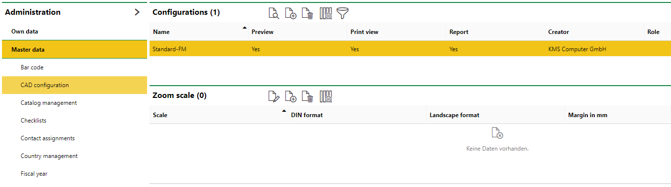
CAD Configuration Page in VertiGIS FM Administration
Create a CAD Configuration
When you create a configuration, it can be used to render any floor plan drawings imported into VertiGIS FM.
To Create a CAD Configuration
1.Navigate to the CAD Administration page (Administration > Master Data > CAD Configuration).
2.In the Configurations section, click the Add (![]() ) icon.
) icon.
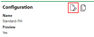
3.In the Name box, enter a name for the configuration.
4.Select the check boxes in the form according to where you want this configuration applied. Refer to Configuration Settings for information on the fields.
5.Click the arrow in the Role menu and select the user role to which this configuration should be available.
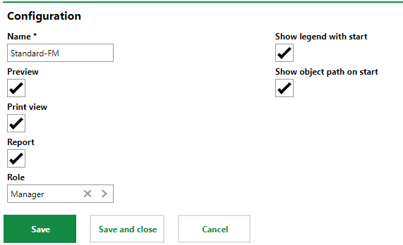
6.Indicate which elements of a drawing you want this configuration to display using the check boxes on the right side of the screen.
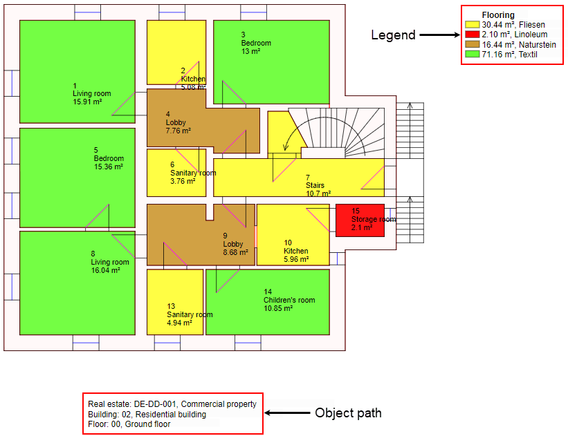
oSelect the Show legend with start check box to have the drawing legend display by default.
oSelect the Show object path on start to have the object path display by defaut.
7.Click Save and Close.
Setting |
Description |
|---|---|
Preview |
Whether the configuration is applied to floor plan drawings in the preview view. |
Print view |
Whether the configuration is applied to floor plan drawings in the print view (the page that opens when the Print Area ( |
Report |
Whether the configuration is applied to floor plan drawings in reports. Ask Katrin to explain. |
Show legend with start |
Whether the floor plan drawing should display the legend when this configuration is applied. |
Show object path on start |
Whether the floor plan drawing should display the object path when this configuration is applied. |
Role |
The user roles that will use this configuration. |
Edit a CAD Configuration
When you edit a configuration, you can change any of the configuration properties you saved when you created the configuration. Additionally, you can manage the layers, attributes, and products to which the configuration is available.
To Edit a CAD Configuration
1.On the CAD Configuration page, double-click the configuration you want to edit in the Configurations section. Alternatively, you can select the configuration you want to edit and click the View Details (![]() ) icon.
) icon.
2.On the configuration details page, click the Edit (![]() ) icon.
) icon.
3.Edit the configuration details as required.
4.Click Save and Close.
Layers, Attributes, and Products
Layer, attributes, and product settings can be managed for each configuration. These settings are accessed on the configuration details page. To access them, double-click one of the existing configuration in the Configurations section on the CAD Configuration page. Alternatively, you can select it and click View Details (![]() ).
).

Layers, Attributes, and Product Sections on the Configuration Details Page
Layer
The Layer section lists the layers that have been created in the DXF Layer section the CAD Administration page. You can turn each layer on or off specifically for this configuration, or you change the order in which the layers display by adjusting the values in the Priority column.
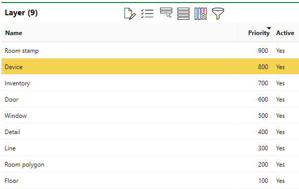
Layer Section on Configuration Details Page
To edit a layer's priority or status, select it and click the Edit (![]() ) icon. You can also change the Active status of one or multiple layers at the same time by selecting the layer(s) and clicking Active Switch Over icon. Any layers with an Active status of Yes are switched or No, and vice versa.
) icon. You can also change the Active status of one or multiple layers at the same time by selecting the layer(s) and clicking Active Switch Over icon. Any layers with an Active status of Yes are switched or No, and vice versa.
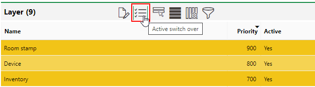
Active Switch Over Button in Layers Section
Attributes
In the Room Attributes, Inventory Attributes, Device Attributes, Window Attributes, Door Attributes, and Employee Attributes sections, all the attributes set to Active in their respective sections on the CAD Administration page are shown.
You can set them to active or not active depending on whether you want them to display in the viewer when this configuration is used.
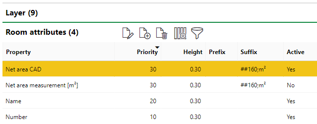
Room Attributes Section on the CAD Configuration Page
Height
The values in the Height column determine the size of the stamp labels in the viewer when this configuration is used. To make the text for the name of the room appear larger, for example, increase the value from the default 0.30 for the Name attribute under Room Attributes.
Colour
The colour selected for an attribute determines the text colour in which the attribute will display on the floor plan drawing in the viewer.
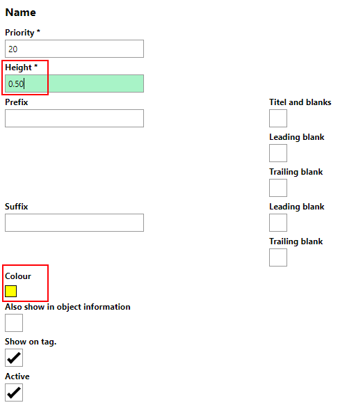
Height and Colour Fields on the Name Attribute Form
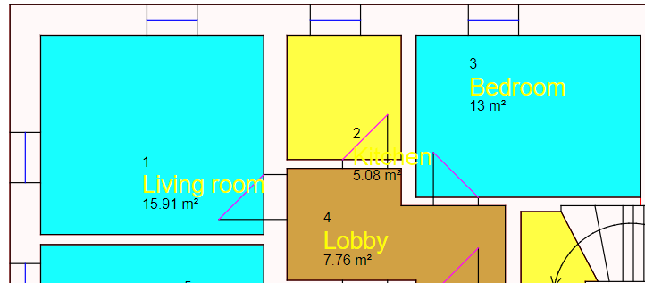
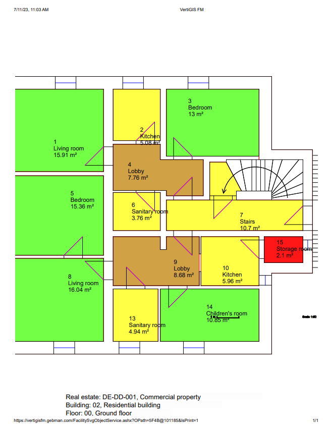
Floor Plan Drawing with 0.50 Height and Yellow Colour for Name Room Attribute
Create New Attributes for the Configuration
You can add new attributes to the configuration for any data included in your drawing and imported into the system.
To Create a New Attribute for the Configuration
1.On the CAD Configuration details page, expand the attributes section for the type of attribute you want to add and click the Add (![]() ) icon.
) icon.
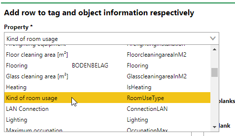
2.In the Property drop-down menu, select the property you want the attribute to display in the viewer.
3.In the Priority text box, specify a priority in relation to the other attributes' to indicate where in the order you want this attribute to display.
4.In the Height text box, enter a number to reflect the size of the attribute as you want it to display in the viewer. This feature can be used to reflect more important information in the viewer. The default value is 0.25.
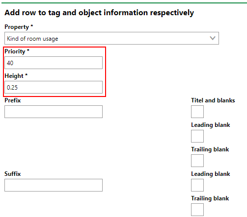
5.Complete the optional form fields as required. You can specify a prefix and suffix for the new attribute or the color in which you want it to display in the viewer.
6.Click Save and Close.
Edit Existing Attributes
To edit an existing attribute for the configuration, select it in the section for its attribute type and click the Edit (![]() ) icon. You can edit the attribute properties for the configuration as required and then save the attribute.
) icon. You can edit the attribute properties for the configuration as required and then save the attribute.
Products
In the Products section, you can specify for which VertiGIS FM products the configuration should be used. The products for which the configuration whose configuration details page you're viewing are indicated in the Product column.
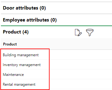
Products for which the Configuration Being Viewed Is Available
If no products are shown in this section, the configuration appears for all products.
Add Products to the Configuration
You can add a product to the configuration if you want the configuration available to users using that VertiGIS FM product.
To Add Products to the Configuration
1.On the CAD Configuration details page, expand the Products section and click the Further Process (![]() ) icon.
) icon.
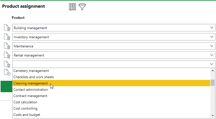
2.Under Product Assignment, click the Add (![]() ) icon.
) icon.
3.Click in the menu for the box you just added and select the VertiGIS FM product you want to add to the configuration.
4.Click Save and Close.
To Remove a Product from the Configuration
1.On the CAD Configuration page, expand the Products section and click the Further Process (![]() ) icon.
) icon.
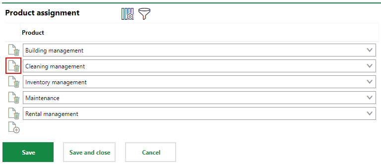
2.Under Product Assignment, click the Delete (![]() ) icon next to the product you want to remove from the configuration.
) icon next to the product you want to remove from the configuration.
3.Click Save and Close.
Zoom Scale
You the Zoom Scale section, you can save scale configurations that determine how floor plans will look on the page when you print them using the viewer. Zoom Scales set the scale of the floor plan image as it will appear on the page, whether the floor plan is being printed as a portrait or landscape paper, and the width of the margins.
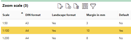
Zoom Scale Section on the CAD Configuration Page
The Zoom Scales you create in this section of the CAD Configuration page are available for selection when you print a floor plan.
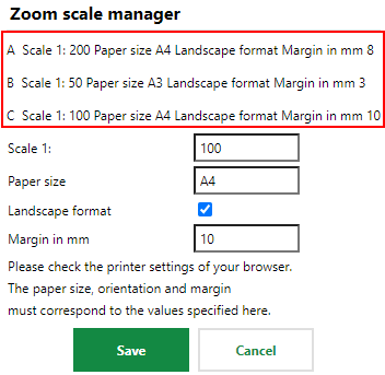
Zoom Scale Selection when Printing Floor Plan
To Create a Zoom Scale
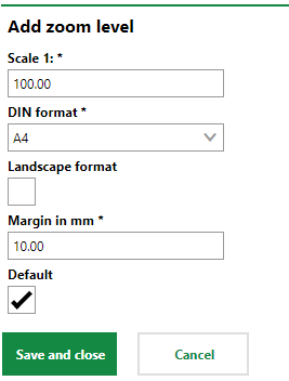
1.On the CAD Configuration page, click the Add (![]() ) icon in the Zoom Scale section.
) icon in the Zoom Scale section.
2.In the Scale 1 box, enter the ratio (1:x) in which you want the floor plan image to display on the page. For example, if you want the image to take up the entire page without the margins, enter 100 to make the ratio 1:100 (100%). Refer to Scale Examples below.
3.In the DIN Format menu, select the format and corresponding size for the page to be printed.
4.Select the Landscape Format check box if you want the page orientation to be landscape. If you leave this check box blank, the page will print as a portrait when you apply the configuration
5.In the Margin in mm text box, enter the width of the margins in millimeters that the page will have when you apply this configuration.
6.To make this configuration the default zoom scale, select the Default check box.
If you create save a new zoom scale configuration with the Default check box, the Default value for a zoom scale configuration that had its value set to Yes is changed to No. Only one zoom scale configuration can be the default.
7.Click Save and Close.
Edit a Zoom Scale
You can a zoom scale configuration by selecting it in the Zoom Scale section of the CAD Configuration page and clicking the Edit (![]() ) icon. When you've edited the configuration properties you want to change, click Save and Close.
) icon. When you've edited the configuration properties you want to change, click Save and Close.
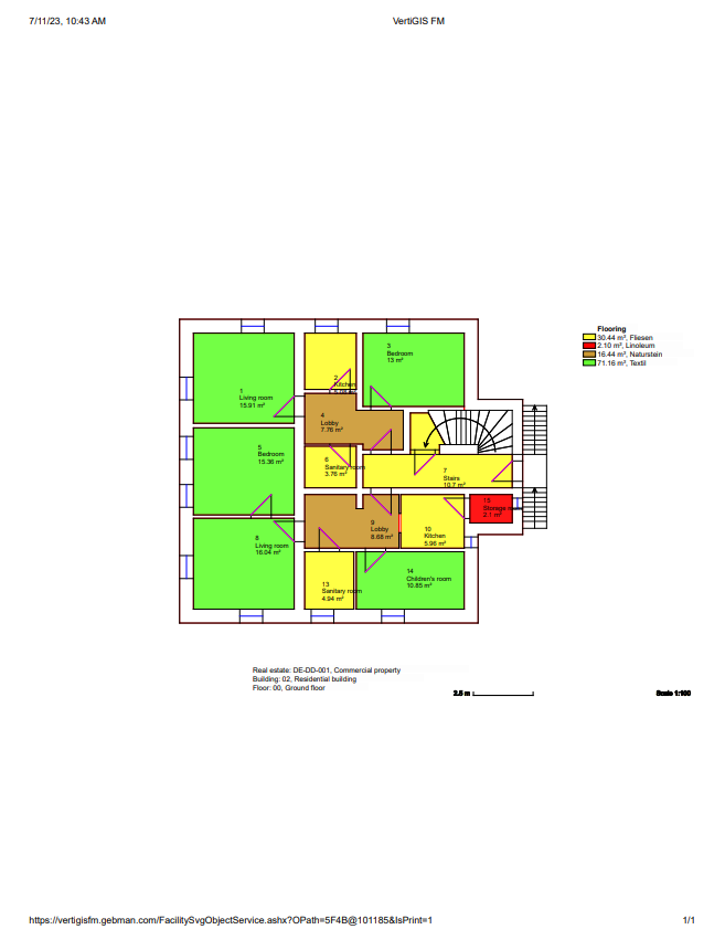
Scale Examples
The scale examples below are all shown with 10 mm margins.
|
|
|
1:100 |
1:200 |
1:50 |