Multilines are a type of geometry used to group multiple, independent line segments into a single feature. You can use them to represent complex linear systems that share common attributes.
All line types can be added in any combination to the multiline.
For example, if you are mapping a transportation network, you can use multilines to represent disconnected road segments that belong to the same route.
To create a multiline:
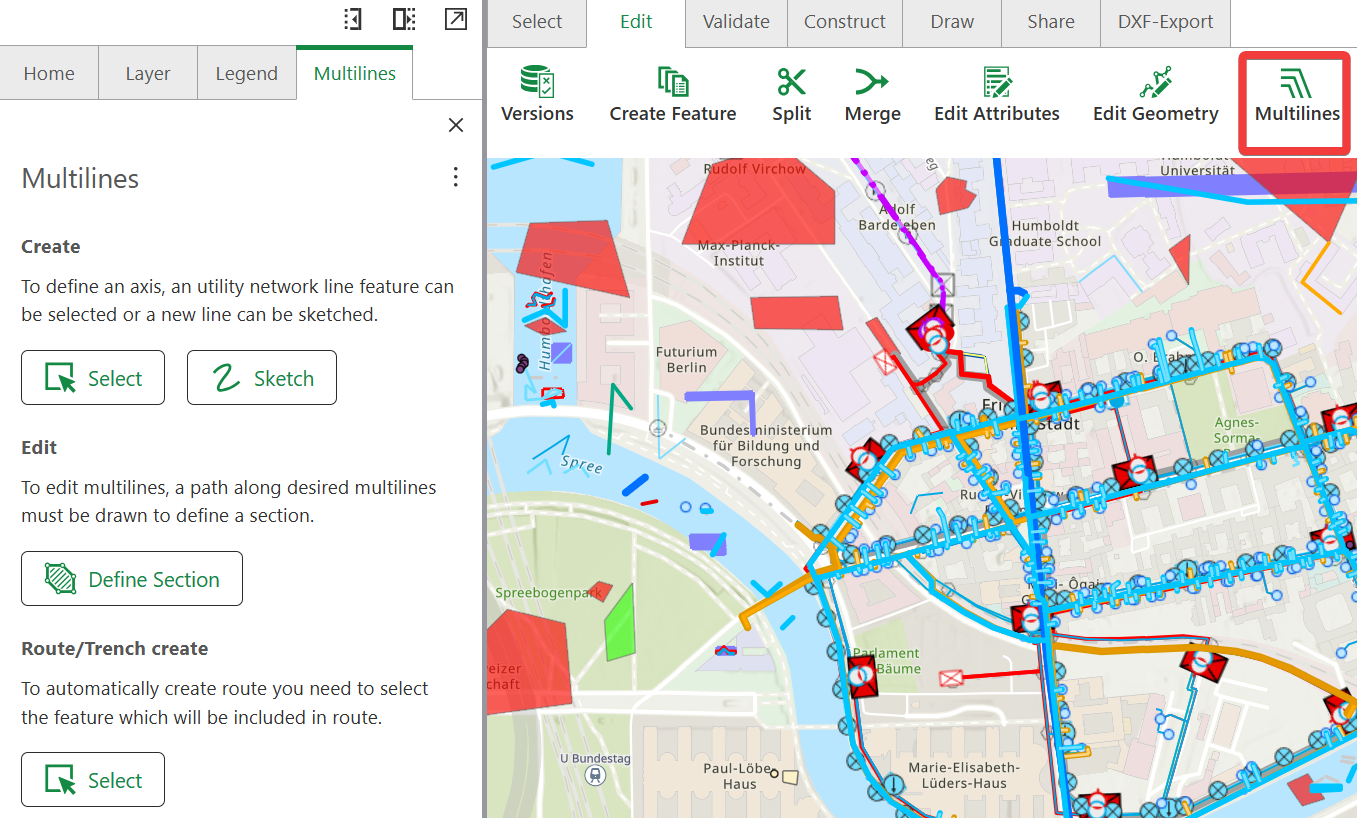
1.Go to Edit > Multilines. In the left side panel, the Multilines tab opens.
2.Use one of the following methods to either select or sketch to create multilines:
•Select: Select an existing line feature in the map as the axis to which parallel lines are to be created.
The creation direction of the selected line feature determines the selected display of the multilines to the left or right of the axis.
•Sketch: Use the mouse pointer to set at least one start and end point, creating a linear axis. You can place any number of vertex points between the start and end points. Alternatively, you can create a linear axis by holding down the left mouse button.
Double-click to finish drawing the lines.
The direction in which the axis is created is decisive for the left-hand or right-hand display of the multilines.
The snapping settings can be used when drawing.
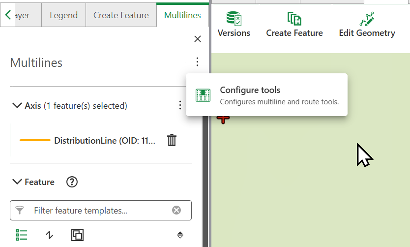
3.Optional: Click Configure tools form the action menu next to Multilines, to adjust the position of created features.
Click on the tool-tip next to Multiline create to learn more about the position of features setting.
4.Add any compatible line feature to the axis by selecting one or more feature templates via the  button in the Features area. The number of feature templates displayed can be restricted using the filter option.
Multilines appear in the Added features section. You can duplicate or delete them as required, as well as, set the hierarchy between the new line features you are creating. This is especially useful when creating a tube with several contained pipes, or a trench which contains multiple cables.
The display of the feature templates depends on the visible layers in the map. Visibility can be switched on or off via the Layer tab.
The drag and drop behavior for multilines distinguishes between assets placement based on the drop position. Dropping a feature on the drag and drop icon assigns it next to an asset, and dropping a feature to the right of the drag and drop icon assigns it as a contained asset.
4.Configure the settings, as described below.
Setting |
Description |
|---|---|
Gap Between Lines |
Defines the distance between lines. This setting is not saved in User Preferences. In subsequent app sessions, this value resets to the default setting. To prevent lines from overlaying over each other in the utility network, the minimum value for gap between lines is 0.01 m.
|
Auto Connection |
When enabled, allows lines to automatically connect to nearby vertices, endpoints, or edges as you create or edit them. |
Tolerance Range |
When enabled, allows lines to automatically connect to nearby vertices, endpoints, or edges as you create or edit them. When sketching a multiline axis that runs parallel to multiple existing features of the same feature type, Auto Connection will automatically create connections to all parallel features simultaneously, eliminating the need to manually connect each parallel line. |
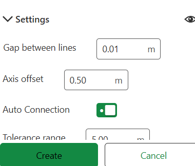
5.Click Create to save the multilines.
See also: Edit Multilines.
Adjust Multiline Configurations
To adjust the configuration of multiline and route/trench tools:
1.Open the context menu and select Configure Tools.
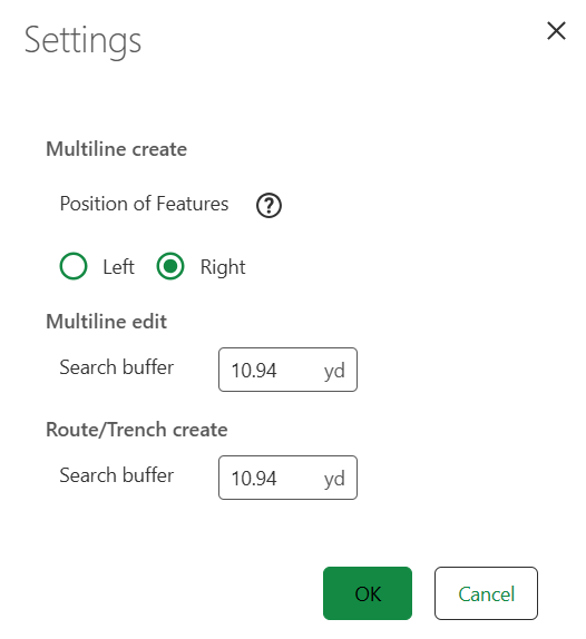
2.Adjust the Position of Features relative to the multiline axis by selecting between:
oLeft: New features are added to the top and left of the axis.
oRight: New features are added to the bottom and right of the axis.
3.In the Multiline edit section, set the search buffer zone around the drawn line section in which the tool searches for parallel line segments. All found lines will be selected for editing the geometry.
4.In the Route/Trench create section, set the search buffer zone around the selected or sketched line for finding parallel line segments. Found segments appear in the selected features list and can be manually deselected if needed.
5.Click OK to save your settings or Cancel to discard changes.
All measurement units are set according to your region defaults during the configuration of your app in Designer, to know more about configuring measurement units, visit VertiGIS Studio Web documentation.
Multiline Tool for Non-Utility Network Features
Multiline Tool works with non-utility network feature, enabling the tool's use with:
•Planning scenarios: Creating multilines for proposed infrastructure that isn't yet part of the formal utility network.
•Overview/reference maps: Working with simplified or cartographic representations of linear features.
•General GIS data: Any linear features that don't have utility network properties.