With the Networks Editor the assets required for a Utility Network can be created. This function, which can be accessed both via the Home tab and via the toolbar, offers predefined feature templates for selection.
To create a feature:
1.Go to Edit > Create Feature.
In the left side panel, the Create Feature tab opens.
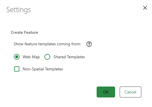
2.Choose whether the feature templates you want to create are provided by the web map, or are shared templates published on the Feature Service by clicking the action menu next to the Create Feature header and then clicking Show settings.
A Settings pop-up is shown where you can choose the options you want.
To know more about shared templates, visit Esri's Editing Templates across ArcGIS.
3.Optional: add non-spatial templates to create features without geometry by checking the Non-Spatial Templates, then clicking OK.
All of your non-spatial templates are shown in the form of tables when clicking All feature templates.
4.Select a Feature Template from the input window by searching for a specific feature template and selecting it with a mouse click or using the keyboard, rotate the feature text by moving the mouse pointer on the map, then place the text by a second click on the map.
Your newly chosen position of the feature template's text is now saved on the map.
The desired feature can be selected from the preconfigured feature templates.
For clarity, feature templates are hidden from invisible layers.
Other functions include:
Button |
Description |
|---|---|
|
Only the feature templates compatible with the selected feature can be displayed. |
|
The complete feature template list can be displayed depending on the layer visibility. |
|
The most recently used feature templates can be listed for quick access by clicking on the button at the top of the list. |
|
Feature templates marked as favorites can be displayed. |
|
The templates can be sorted alphabetically. |


Instead of selecting a template from the complete template list, the Compatible Feature Templates mode can be used. Only the feature templates that can be linked to the feature selected in the map using point selection from a network topology perspective are then offered.
The active feature template is marked with a green bar and can now be used to capture a feature of this type in the map.
Each feature template is assigned to a specific layer. The assigned layer is displayed in square brackets after the template name if the detail view  is active.
A layer can be switched off and therefore not visible or not visible due to the scale settings. If the layer belonging to the feature template is not visible due to the currently set map scale, the message "Zoom to scale range of the layer" appears below the template.
The feature templates are either Network Feature that are part of the utility network, or Non-network-Features (e.g. an info line). The different capture rules described below are used to capture these features.
5.Optional: Click Shared Templates, then choose one of the Group Templates or the Preset Templates for faster placement.
The shared templates are predefined configurations that allows you to create multiple related features and their associations in a single step. For more information, see Esri's shared templates documentation.
You can place preset templates that include dimension features, provided that the correct configuration for them is in place.
You can place preset templates that include annotations, provided that they are without leaderlines, and the correct configuration for them is in place.
When publishing shared templates, ensure that the decimal separator settings match on both the feature service machine and the publishing workstation. Mismatched settings (e.g., comma vs. period) can cause numeric values to interpreted incorrectly.
Choose Group Templates when you want to create a primary feature together with additional related features in a single step, and automatically establish associations during placement.
Choose Preset Templates when you want to insert a predefined set of features with all its geometry, attributes and associations from the original configuration.
a.Network feature
If a template for capturing a network feature is selected, the mouse pointer changes to a cross symbol with a surrounding circle. The selected point, line or polygon shaped feature can now be placed or drawn in the map. After finishing by double-clicking, the new object will be displayed in the map with the symbology corresponding to the selected feature template.
The collection process can be aborted with the Esc key.
Newly created lines are automatically connected to the appropriate terminals if the line end points are geometrically connected to network points for which terminals are defined.
If a newly created line cannot be clearly connected to a terminal, the terminal dialog is displayed. The user can manually connect the line to the desired terminal. See also chapter Connecting Terminals.
b.Non-network feature
When selecting a template for a non-network feature, snapping is deactivated by default. The mouse pointer is simply displayed as a cross symbol and the desired object can be placed anywhere on the map.
The Snapping for non-network features can be activated with pressed Alt Key. Then the mouse cursor changes to a cross symbol with a surrounding circle.
7.Snapping Options
While sketching, the snapping options can be changed using the toolbar on the right-hand side of the map. The following options are available:
Button |
Description |
|---|---|
|
Current state is Snapping ON. |
|
Current state is Snapping OFF. |
|
If this function is switched on, Utility Network Assets are snapped according to the connectivity rules of the utility network. The "Snapping ON" function must be active for this mode to be effective. |
|
If this function is switched off, Utility Network Assets snap all the layers on the map. The "Snapping ON" function must be active for this mode to be effective. |


Snapping can also be deactivated by holding down the Alt key until snapping deactivates.
8.Collect feature attributes
After the geometry is created, the predefined fields for attribute input open in the left side panel.
9.Save feature by clicking Save.
This stores the feature with generated geometry and associated attribute data to the database.
In principle, the geometries of objects in a utility network must have Z coordinates in addition to X and Y coordinates. VertiGIS Studio Web does not generate Z-coordinates by default when capturing objects.
If the following error message appears, the Feature Service must be configured to accept Z coordinates. 
The following option is available in the ArcGIS Server Manager when configuring the feature service:
