Split Feature
This function can be used to split network features using a point or one or more feature(s) using an intersection line. You can split both linear features (lines) and polygon features (areas such as ProtectiveTubes, TrenchBoundary, and other polyline features).
To split features:
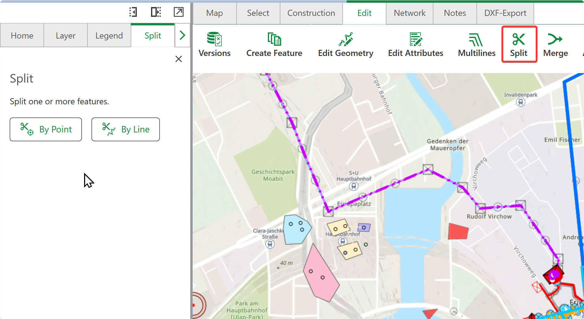
1.Go to Edit > Split.
2.From the left panel, choose between split by point or by line:
▪By Point: The mouse pointer changes to a circle symbol. Snapping is automatically activated and the network feature to be split is highlighted when you move over it. The mouse pointer can now be placed on the feature with a mouse click.
The network rules validation running in the background may cause a slight delay when executing the snap function.
▪By Line: The mouse pointer changes to a cross symbol. You can now use the mouse to draw an intersecting line over one or more feature(s). Double-click to end the line.
Split with line can split both linear features and polygon features (areas):
•Linear features are split where the line intersects them
•Polygon features are only split if they are completely intersected by the line
When splitting, the function is first applied to selected features, otherwise to intersected features.
If an intersecting line is placed over several unselected linear features, all these lines are split.
If only one of these lines is selected, only the selected line will be split.
•A confirmation prompt appears asking if you really want to split the selected feature(s), click OK to save your changes.
If one or more attachments are present in the line you split, the attachments are copied to the resulting split lines.
If one or more relations are present in the line you split, the relations are copied to the resulting split lines. If a cardinality violation occurs by splitting, you are asked in a prompt to choose to either keep the relationship to one of the segments, or to cancel the split operation.
Handling Cross Sections When Splitting Structure Lines
When you split a structure line that has cross sections attached:
•Cross Section Data Distribution: If a structure line feature with cross section attached is split:
oThe JSON attachment is kept for the segment where the reference line is located.
oThe other segment gets a automatically generated cross section.
•Data Validation: The system does not automatically check for errors in outdated cross section data structure. If you encounter issues, you can reset the cross section data using the Cross Section Panel.
•Placement Block Considerations: If a Placement Block exists in the cross section data, the system will automatically clear it when the split line geometry no longer matches the original reference line, preventing geometric inconsistencies between the cross section data and the actual line segments.
After splitting structure lines with cross sections, review your cross section data in the Cross Section Panel to ensure accuracy and make any necessary adjustments.
During split operations, associations will simply be carried over using shallow copying. For instance, when a pipe A — associated with X, Y, and Z — is split into pipes B and C, both B and C retain the associations with X, Y, and Z.
Areas can only be divided with a cutting line. When using "Split with Point", the system checks whether a feature with line geometry is found underneath. If no line geometry is found, you will receive an error message: "Error splitting a feature with a point! No feature with line geometry found."
Handling Linked Annotations When Splitting Features
When you split a line/polygon with linked annotations:
•Linked Annotation Placement: The annotations are linked to the newly split features based on their geometrical closeness, to get to the nearest Annotation/Line segment combination:
oPolygon split: The center point of the polygon is taken as a reference to determine to which polygon the annotation is placed.
oLine split: The linked annotation is linked to the line with the smallest projected distance.
•Annotation Text: Annotation text is only updated if it is not triggered automatically.
Split Policy for Domains
The table below provides information on split policy for attribute domains.
Policy |
What Happens |
Works with |
Example |
When to Use |
|---|---|---|---|---|
DefaultValue |
The attributes of the resulting features take on the default value for the attribute of the given feature class or subtype. |
Coded & Range Values. |
A pipe with status "In Service" is split into two pieces. Both new pipe segments get the default status "Planned" instead of keeping the original "In Service" status. |
When the original value no longer applies logically to the new segments. |
Duplicate |
The attributes of the resulting features take on a copy of the original object's attribute value. |
Coded & Range Values. |
Split plastic pipe - both segments retain the same material (plastic). |
When the attribute should remain unchanged (e.g., material type). |
GeometryRatio |
The attribute values of the resulting features are split proportionally based on geometry. |
Range Values ONLY. |
A 10-meter pipe divided in a 60/40 split results in 6-meter and 4-meter segments. |
When the attribute value should be proportional to the size of each segment. |
The value five is the default value of the system.
Insert point feature – split line
The section below describes the splitting behavior of the Networks Editor and the rules it is based on. In order to clarify this, we use an example of a use case where the user creates a new network point feature in the middle of a line, via snapping, and not at its end points.
Conditions and procedures
Possible subsequent actions:
1.Automatic split of the line.
The Networks Editor automatically takes over splitting.
2.Optional split of the line.
The user is free to decide whether he wants to split the line. From a network topological point of view, both (line split/no line split) are correct and wouldn’t create a dirty area.
3.No split of the line.
From a network topological point of view, the insert of network point must not split the line.
4.Error message.
It is not possible to insert the point from a network topological point of view (neither splitting nor non-splitting).
The follow-up action that is performed depends on several factors:
a.Does the network point have connection points (terminals)?
b.Is there a junction-edge rule?
c.Is there a junction-edge-junction rule?
d.What edge connectivity does the line have (Any vertex—Features/End vertex—Features)?
Terminals |
Junction-Edge Rule |
Edge-Junction-Edge Rule |
Edge Connectivity: Any Vertex |
Edge Connectivity: End Vertex |
Action |
|---|---|---|---|---|---|
X |
(X) |
X |
X |
|
Automatic split |
X |
(X) |
X |
|
X |
Automatic split |
|
|
X |
X |
|
Automatic split |
|
|
X |
|
X |
Automatic split |
|
X |
|
|
X |
Automatic split |
|
X |
X |
X |
|
Optional split |
|
X |
|
X |
|
No Split |
X |
|
|
|
|
Error |
X |
|
|
X |
|
Error |
X |
|
|
|
X |
Error |
X |
X |
|
X |
|
Automatic split |
X |
X |
|
|
X |
Automatic split |
|
|
|
|
X |
Error |
|
|
|
X |
|
Error |
Merge Feature
This function is used to merge split network features, this is useful for when you plan on extending an existing structure.
To merge lines/areas:
1.Go to Edit > Merge.
The mouse pointer changes to a circle symbol. Snapping is automatically activated and the feature to be merged is highlighted when you move over it.
2.Select the lines/polygons you want to merge.
A table comparing the source and target features is shown in the merge menu.
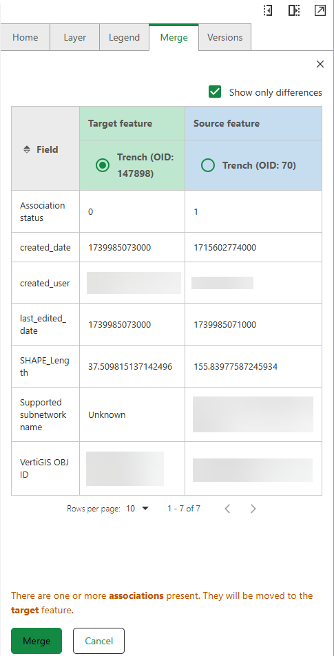
You can choose to compare only attributes which differ between both features, or choose to compare all attributes in the table by clicking on the Show only differences check-box.
If there are more than one cross section present, you have to decide which one to keep, as there can only be one cross section present per network feature.
3.Choose which feature is the target feature (highlighted in green). The remaining feature is automatically assigned as the source feature.
If there are one or more associations, relationships, and/or attachments present in one of the merged features, they will be moved to the target feature that you choose.
When merging lines, the tool detects the suitable intersections at line ends, and the nearest valid point is used. If no intersection can be created, an error message is displayed.
When merging polygon features, make sure the areas overlap, otherwise, the merge cannot happen.
The target feature keeps all of its attributes after the merge is complete.
When merging lines with multiple annotations, all annotations are linked to the newly merged lines.
In the Split and Merge features, you can split Utility Network layers, as well as, simple feature layers.
Merge Policy for Domains
The table below provides information on merge policy for attribute domains.
Policy |
What Happens |
Works With |
Example |
When to Use |
|---|---|---|---|---|
Area Weighted |
The attribute of the resulting feature is the weighted average of the values of the attributes from the original features. |
Range values ONLY. |
Two parcels are merged where Parcel A covers 40% of the total merged area with a ground value of 1000 €/m², and Parcel B covers 60% of the total merged area with a ground value of 500 €/m². The merged parcel gets a weighted average value of (0.4 × 1000) + (0.6 × 500) = 700 €/m². |
When you want a size-weighted average of the original values. |
Sum Values |
The resulting feature's attribute is the sum of the original features' attribute values. |
Range values ONLY. |
Merging a 12 meter pipe with an 8 meter pipe results in a new 20 meter long pipe. |
When you need to add attribute values together (e.g., total capacity). |
Default (Target Feature Adoption) |
The attribute of the new feature is adopted from the designated target feature. |
Coded & Range Values. |
Merging two pipes results in a new pipe that inherits all properties from the pipe you selected as the target. |
When you want to preserve all attributes from a specific feature. |