A cross-section describes how the assets are arranged inside a structure line, such as a trench. A cross-section represents the real view of an open trench in a generalized grid view. Cross-sections can also be drawn, labeled and printed on the map.
To edit cross sections:
1.Go to Network > Cross Sections. In the left side, the Cross Sections panel opens.
2.Load the cross sections of structure lines by any of the various available functions for selection.
Button |
Description |
|---|---|
|
Load the desired cross sections with a mouse click on a structure line or by drawing a rectangle over a map area. |
|
Load the cross sections of structure lines that are already selected in the map from another step or with another selection function. |
|
Load the cross sections on all the available structure lines in the current map extent. |
|
All loaded structure lines and cross section information are removed from the results list. |


3.The result set of the structure lines found by the respective selection function is divided into the following parts:
i.Panel title
The panel title Cross Sections shows the number of assets loaded in brackets.
The action menu of the panel title.
Button |
Description |
|---|---|
|
Displays all loaded cross sections in the map. The cross sections graphics are generated in the temporary graphical layer cross section. |
|
Removes all cross sections from the map. The temporary graphic layer cross section is removed. |


ii.Active cross section
The error or warning icon displayed behind the title Active cross section indicates missing, invalid or inconsistent cross section descriptions (attached JSON file).
The tool-tip for the icons contains a detailed description of the warnings and errors.
Icon |
Description |
|---|---|
|
A cross-section description for the active structure line is missing. The displayed cross-section grid is generated by the system using the containment associations. |
|
There are data inconsistencies between the containment associations and the cross-section description. |

In the following section, the active structure line for which the cross section is displayed in the panel is shown below with its layer symbol and label.
The action menu of the active structure line has the following:
Button |
Description |
|---|---|
|
Remove active structure line from the result list. |
|
Zoom to the active structure line. |
|
Pan to the active structure line. |
|
Briefly highlight active structure line on the map. |
Show the attribute fields of this structure line in a read-only mode. |
|
|
Create or delete a cover stone for the selected cross section. The cover stone is set to any grid cell of the cross section. Click on the grid edge you want to place the cover stone to. To view the cover stone on the map, click Display/Update cross section. |
|
Display or update the cross section of the active structure line in the map. |
|
Zoom to the cross section representation. |
|
Edit and save the cross section geometry of the active structure line in the map. This functionality only works for already displayed cross sections on the map, if no cross sections are shown on the map, you need to use the Display all cross-sections feature first. |
|
Draw a reference line on the map, from the cross section structure line to the cross section. |
|
Rotate the view direction on the cross section 180 degrees. |
|
Remove the cross section of the active structure line from the map. |
|
Save your current description for the cross section of the active structure line in the map. |
|
Reset the description for the cross section of the active structure line in the map to the default state. |


iii.All loaded structure lines
The arrow keys can be used to switch between the loaded structure lines.
The circular digit highlighted in green indicates that the information displayed belongs to the Active cross section. This currently active structure line is highlighted on the map.
4.In the Cross Section area, the arrangement of the contained assets inside a structure line is displayed in a grid view. If an asset is clicked on, this asset is highlighted in the content section and on the map.
Inconsistencies between the cross section description and the containment associations are indicated directly in the grid with an error icon.
To remove a component from the active cross section, drag and drop said component outside of the cross section representation in grid view. The asset is then placed in the Unplaced assets tab.
Contained assets that are not placed in the cross section are listed below under Unplaced assets in cross section.
If there is no cross section description for the structure line, the displayed cross section grid is generated by the system. 
If a structure line is placed in the cross section, which itself contains additional assets, a plus icon is displayed. The plus button displays the content of this structure line as a separate grid. The content section also shows the content of this structure line. The view can be switched back to the cross section level using the minus icon.
5.In the Content section, the contained assets for the active structure line are displayed in a hierarchical tree view based on the Containment Associations. Similarly, In the Unplaced assets section, contained but unplaced assets for the active structure line are displayed in a hierarchical tree view based on the Containment Associations. If an asset is clicked on, this asset is highlighted in the cross section and on the map.
The action menu of the active structure line has the following:
Button |
Description |
|---|---|
|
Zoom to the active feature. |
|
Pan to the active feature. |
|
Briefly highlight active feature on the map. |
Edit the attribute fields of the selected feature. |
|
|
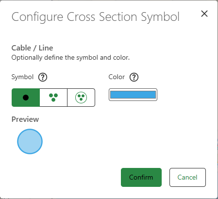
Configure the symbol and the color of the selected cross section. The available symbols for cross section assets are as follows:
|
|
Display the cross section of the active structure line in the map. |
|
Remove the cross section of the active structure line from the map. |
|
Save your current description for the cross section of the active structure line in the map. |
|
Reset the description for the cross section of the active structure line in the map to the default state. |


To arrange the container assets of a structure line in a grid:
1.Drag and drop an asset from the list of Unplaced assets, or reposition an asset from the Active cross section view in an empty grid cell.
Repositioning an asset in an occupied grid cell is not allowed, choose an empty grid cell or create a new one if none is available.
2.Your new asset arrangement is now saved.
If a JSON attachment file exists, you have to save the changes in the file after each new change.
You can view and edit assets of a non-spatial nature directly in the cross sections panel.