Use Station Entry to connect existing network lines to a station boundary in a single operation.
A station entry defines how network lines are routed into a station. Instead of manually splitting each line and repositioning its endpoint, select the side of the station where the lines should enter, select the lines, and specify the spacing between them.
Networks Editor then:
•Splits each selected line at the station boundary.
•Redraws the segments so that they run parallel and enter the boundary at an even spacing.
•Creates a connection junction where each line meets the boundary.
Before you begin
Make sure that:
•A station boundary already exists. If necessary, create one using Create Feature on the Edit tab.
•If the station boundary layer is scale dependent, zoom to a scale at which the layer is visible.
•The network lines that you want to connect to the station boundary already exist.
Open the Station Entry panel
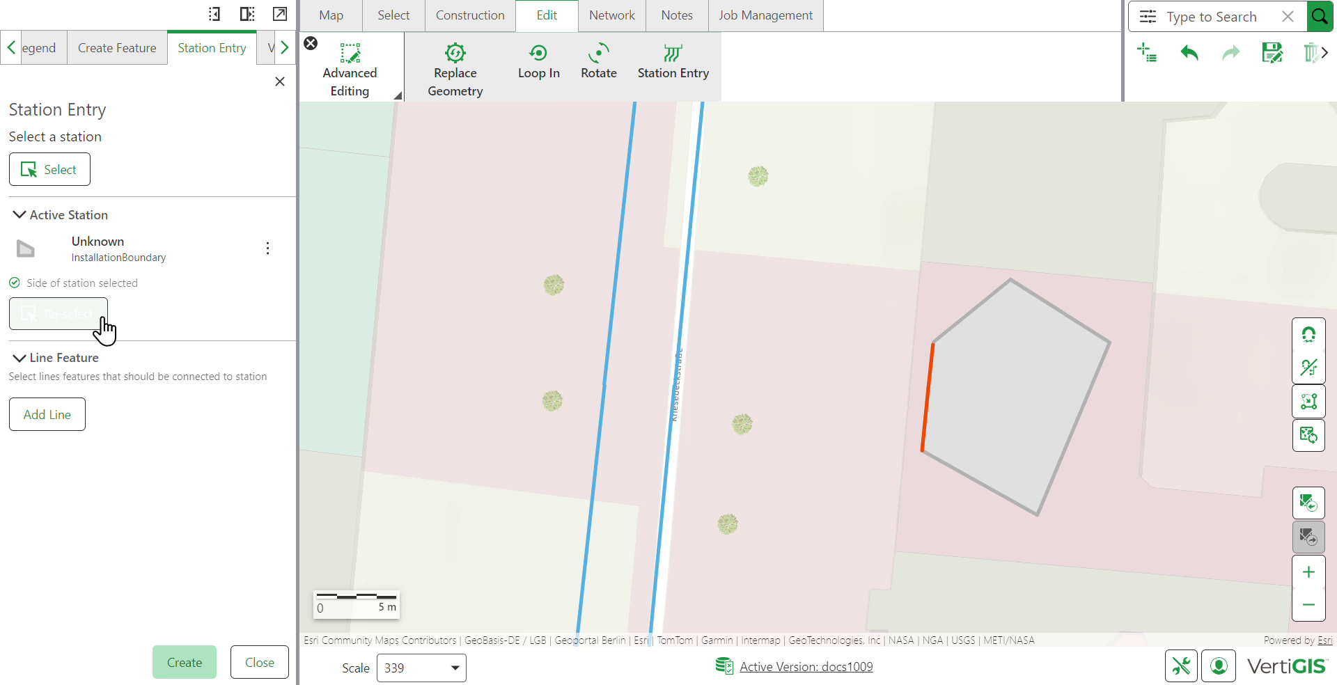
To open the station entry panel:
1.Select the Edit tab.
2.In the Advanced Editing group, select Station Entry.
The Station Entry panel opens on the left.
Connect lines to a station
Step 1: Select the station
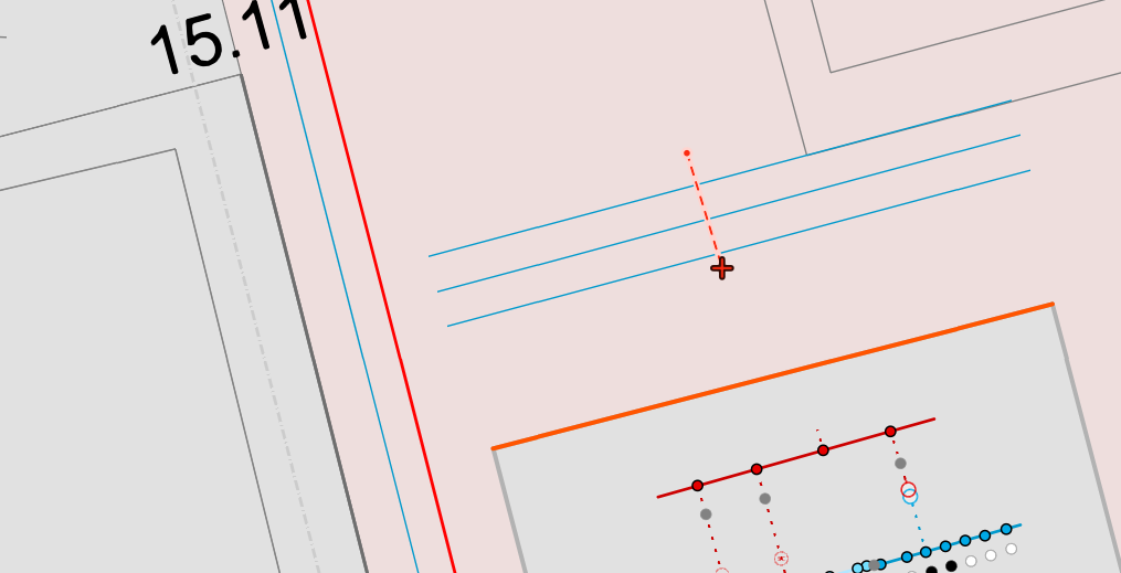
To select a station:
1.In the panel, select Select.
2.Select a Station Boundary.
The station appears under Active Station. At this point the panel shows that no side of the station is selected yet.
If nothing is selected and the station boundary layer is scale dependent, check the map's zoom level.
Step 2: Select the side of the station
A station boundary has several sides, so you must select one of the edges as the entry point for features such as pipes and cables.
On the map, select the side of the boundary that faces the lines you want to connect. Confirm the message Edge segment selected successfully.
The selected side is highlighted on the map, and the panel status changes to Side of station selected.
Select the side that faces the lines. If you select a side that points away from the lines, the editor may fail to calculate the preview and/or connect the lines.
To choose a different side, select Re-select and then select the new side on the map.
Step 3: Add the lines
The Line Feature section becomes available after a side is selected.
Networks Editor supports two methods to add lines that should be connected to the station:
•Straight selection line: Draw a selection line across the line features you want to connect. Each line is split where the selection line crosses it, and both resulting segments are routed into the station.
Selection |
Result |
|---|---|
|
|
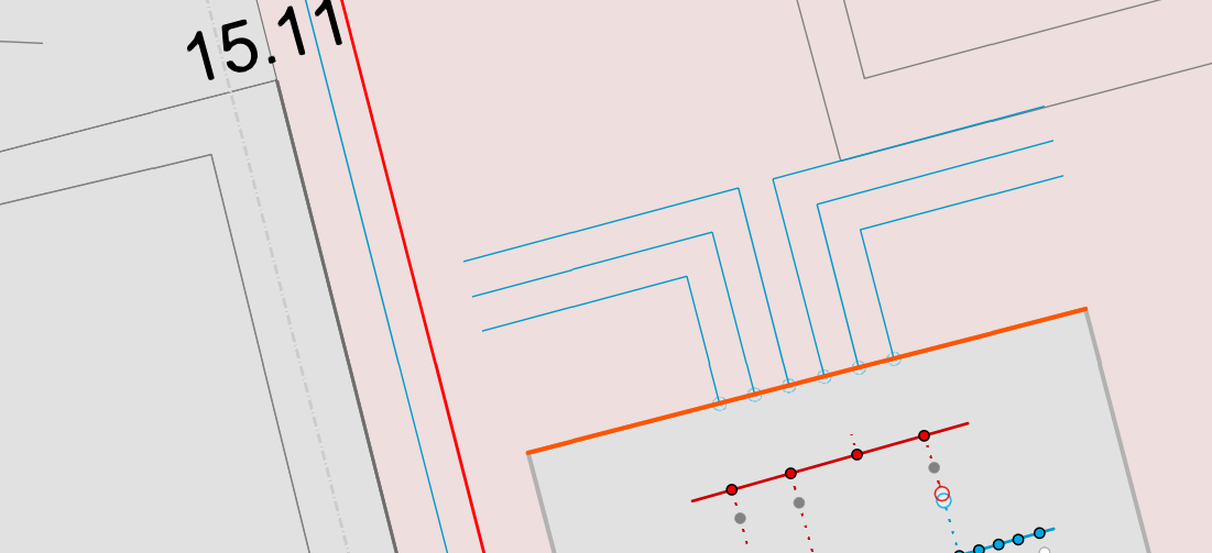
•V-line: Draw a V-shaped selection line across the line features. Each line is split where the V crosses it, but only the segment on the side opposite the V's vertex is routed into the station; the segment on the vertex side is discarded. For example, if the V's vertex points to the right, the left segments are entered and the right segments are removed.
Selection |
Result |
|---|---|
|
|
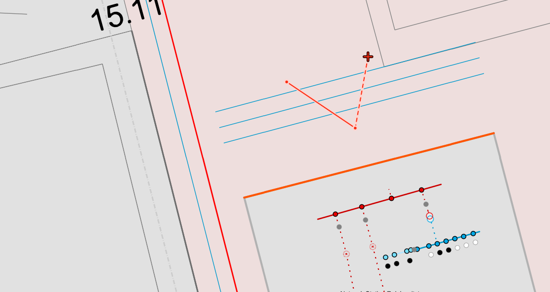
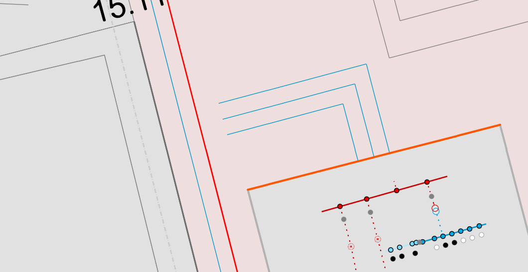
To modify line selection:
•Select Add Line again to add more lines to the selection.
•Select the minus button next to a line to remove that line.
•Open the context menu next to a line to zoom to it or highlight it on the map.
•Select Remove all to clear the list and start again.
Under Settings, enter a value in Gap between lines. This is the distance between adjacent lines where they enter the station. The default is 0.5 m. The unit follows the measurement system that is configured for your profile.
Only the lines within a distance of 50 m from the station boundary are included in the preview.
Use the eye icon to show or hide the preview while you adjust the value.
Step 4: Create the connection
To discard the operation and keep the original geometry, select Cancel.
To create the connections, Select Create.
The result of the operation depends on the type of line selection feature used.
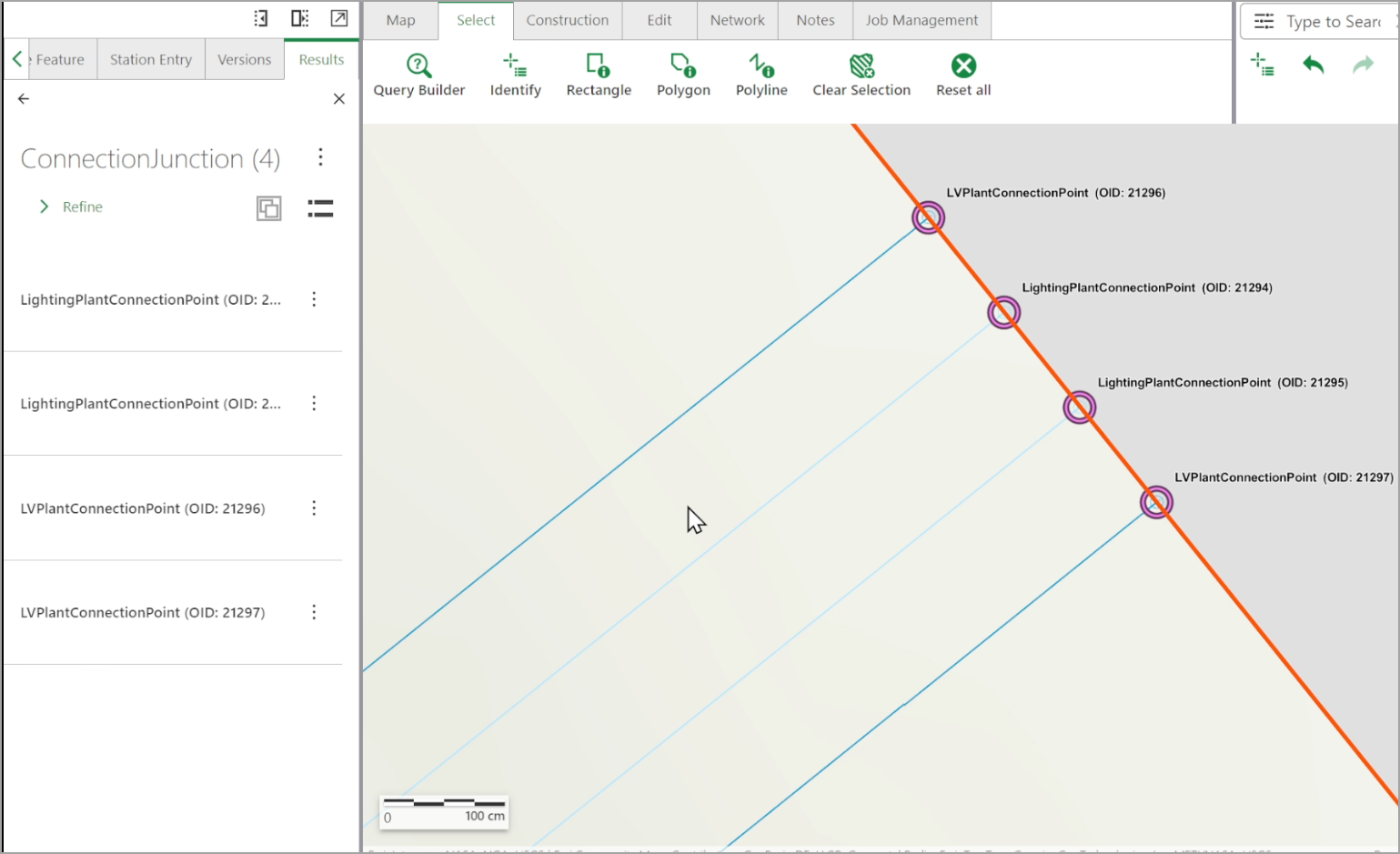
Further, the connection junction matches the type of the line for connection points. For instance:
Line layer |
Connection junction created |
|---|---|
LightingCable |
LightingPlantConnectionPoint |
LVCable |
LVPlantConnectionPoint |
Other domain line types follow the same pattern: the junction always matches the type of the line that it terminates.