This function is only for new multilines created in the same session.
You can create a route/trench for newly created multilines. You can easily identify which cables or pipes belong to a specific tube or trench and modify them as needed.
For our example in the procedure below, we create multiple cables (LVCables) and bundle them together in a trench, you can also use trench containers to organize features hierarchically.
To create a route/trench:
1.Create a multiline (in our example, we create three LVCables)
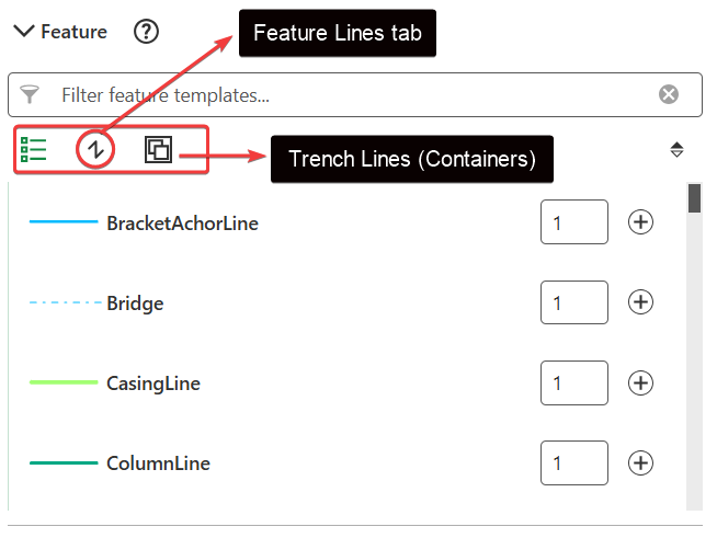
If you select a trench as your axis during multiline creation, it automatically becomes a container. The Feature area will show two tabs: Feature lines (standard lines) and Trench lines (containers).
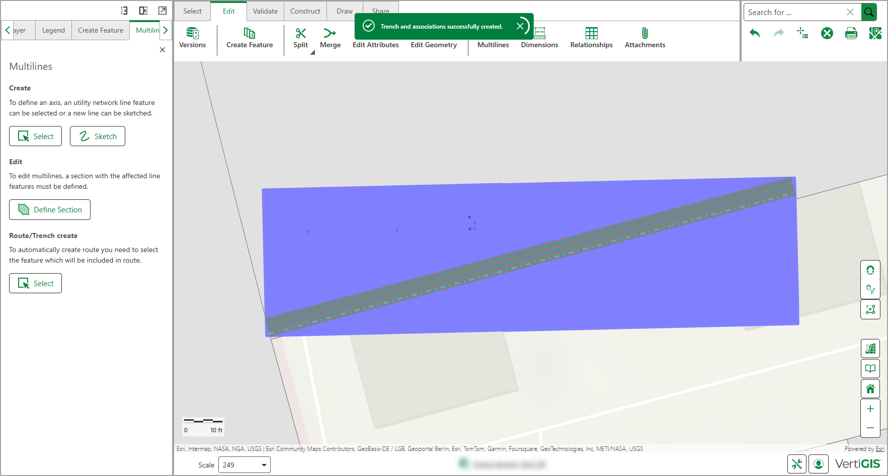
2.Go to Edit > Multilines > Route/Trench Create and click Select.
3.Select the multiline you just created.
You can reload your results by pressing on the button  to select a new baseline feature if needed.
4.Optional: Click Configure tools form the action menu next to Multilines, to adjust the search buffer.
Click on the tool-tip next to Route/Trench create to learn more about the search buffer setting.
5.Automatic Feature Detection: The system creates a search area around the route base and detects nearby features running parallel to it. This search area is divided into logical segments, where features remain consistently parallel. Each segment is visualized on the map as a temporary polygon.
A new segment is created when:
oA feature is no longer parallel.
oA feature exits the search area.
oA feature starts or ends.
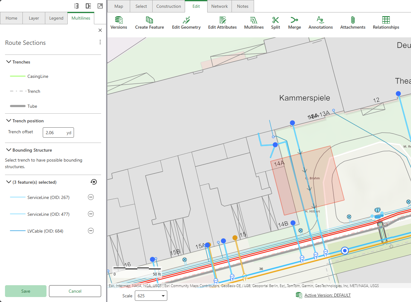
6.Optional: Select the route/trench structure you want to create. In our example, we create a Trench.
If you do not select a polygon or area as a graphical representation of the route/trench, it appears as a line.
The table below describes the route/trench options.
Setting |
Description |
|---|---|
Trenches |
Optional: You can use the Trench and Tube settings to create a graphical representation of a trench area or tube. |
Trench Position |
The Trench Offset is the distance of the trench from the trench axis. |
Bounding Structure |
Optional: Select Trench or Tube to view its aerial representation. Otherwise, you can see the trench represented as a line. |
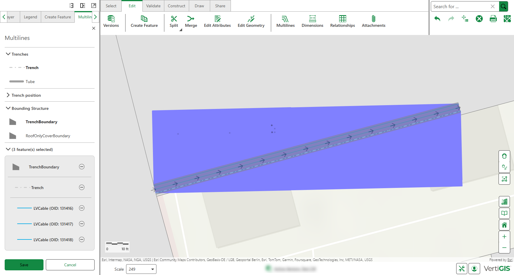
Feature(s) selected |
Displays the features included in the trench/tube. Features placed in trench containers during multiline creation appear indented with gray background borders to show hierarchy. You can remove the feature or selection of tube/trench. |
7.Optional: Use the Sketch tool to define a specific section of the feature to be covered by the trench. Click Sketch, then draw the desired area directly on the map.
A trench is created over a part of the feature, rather than its entirety.
This tool is especially useful when placing a protection tube only at the crossover point where pipelines or cables run beneath a street to provide targeted coverage.
8.Click Save.
The figure below shows how the features are connected within the topology. All lines are linked to the trench line through containment associations (created automatically when using trench containers in multilines). If a trench polygon is present, it contains the trench line.
When adding feature lines to trench, they are validated using the same rules applied during route or trench creation.