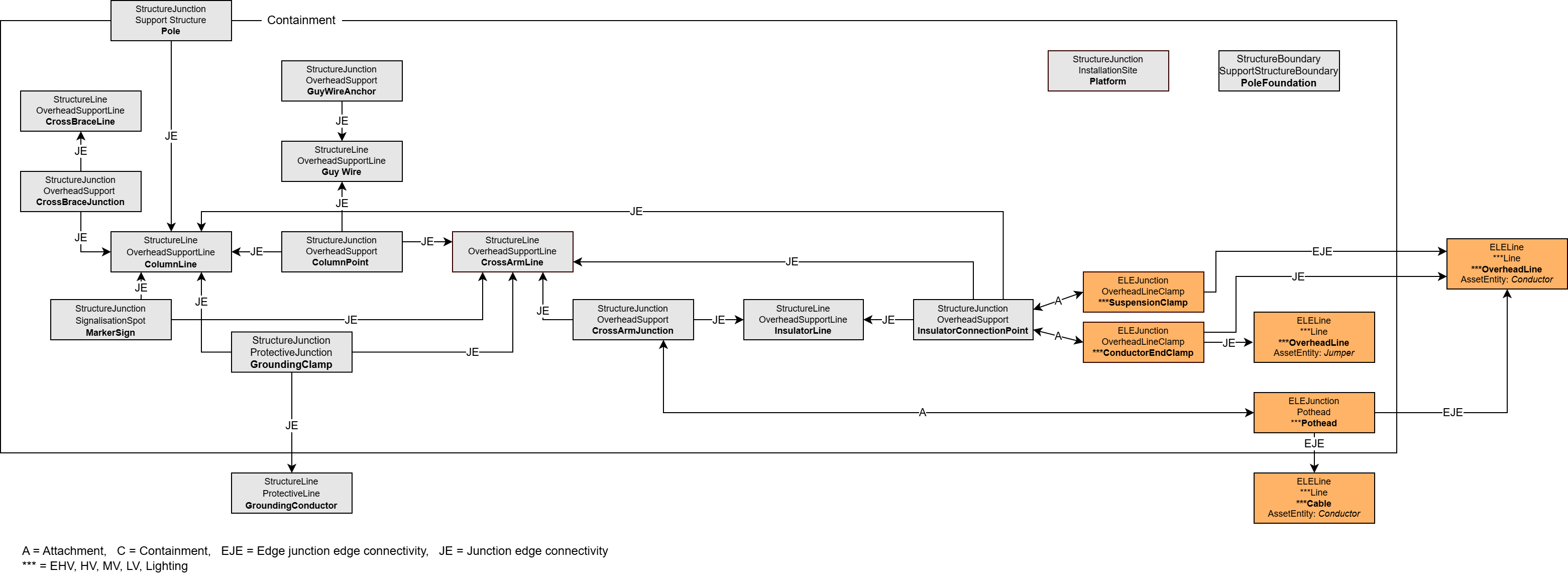
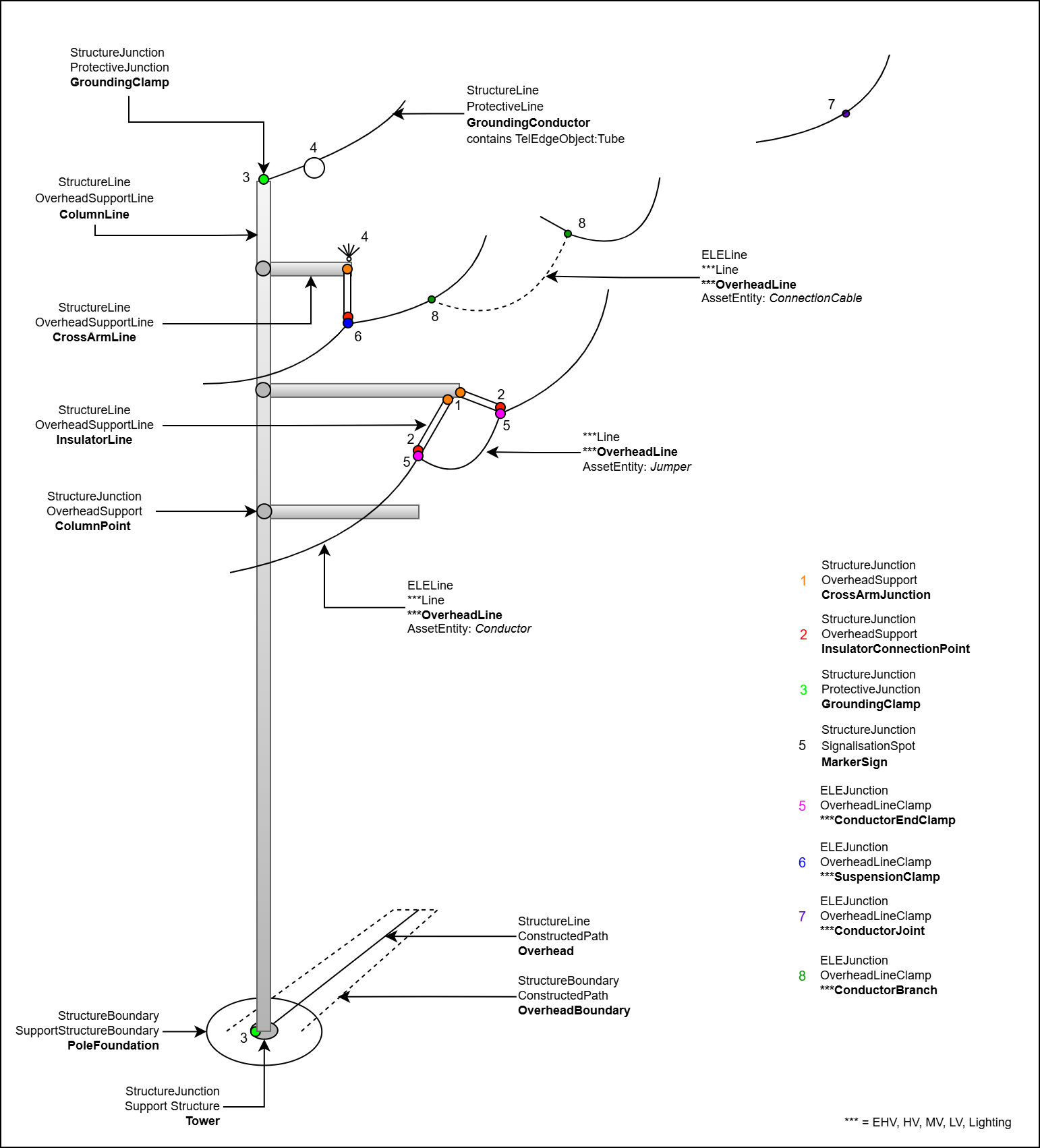
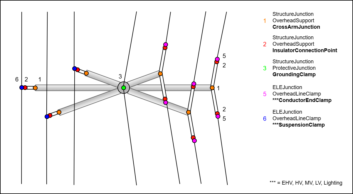
To model the entire tower, the structural components are first recorded. One or more vertical ColumnLines are created at or above the base of the supporting structure. The crossarms (CrossArmLine) are connected to the corner post using a ColumnPoints (only required for snapping). The CrossArmJunction is located at the end of the crossarm and is used to connect the insulator (InsulatorLine) to the supporting structure. An auxiliary point is required for the transition to the electrical network. The InsulatorConnectiontPoint is located at the end of the insulator and is directly connected to the terminal of the electrical network. Its type is determined by the type of supporting structure. In the case of a guyed tower, the cables end and an EndClamp is used. In the case of support towers, the cable is only suspended but not broken. The vertices of the ELELine are therefore connected to a SuspensionClamp. The ground wire, on the other hand, is part of the structural network, not the electrical network. The GroundingClamp therefore sits directly on the corner post or boom and holds the ground wire. The connection to the grounding rod at the base of the pole is also made via the GroundingClamp. Conductor, Jumper, and ConnectionCable are suitable as AssetEntities for the ELELine. Flight warning balls or bird protection can be modeled using MarkerSigns. Complete capture in 3D:
Complete capture in 2D:
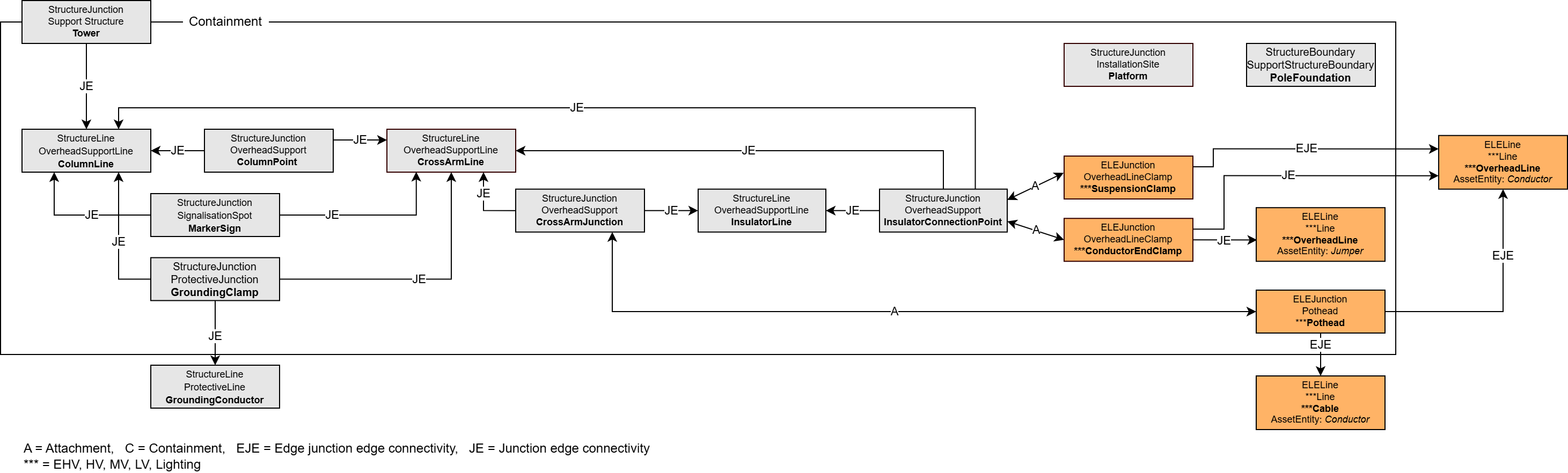
The primary element of the structure is the structural base point, the SupportStructure Tower. All other components are contained within this as containment. Directly connected to this point via a junction-edge connection (JE) is the ColumnLine. At this mast, the ColumnPoints are also connected via JE connections, which are required to attach the outriggers CrossArmLine. The outrigger, in turn, can serve as containment for all elements installed on it. The CrossArmJunction are located on it. These are needed to attach the insulator InsulatorLine. At the other end of the insulator, an InsulatorConnectionPoint is required to connect the clamps from the electrical network via an attachment rule (A). On the guyed mast, the ropes terminate at the ConductorEndClamps, with both ends connected to each other via a jumper. The jumper can also be part of the boom containment, but the ropes cannot, as they are attached to two different masts. On the support mast, the rope, which does not end here, is connected via an edge-junction-edge connection (EJE). The InsulatorConnectionPoint and thus the insulators can also be installed directly with the CrossArmLine or the ColumnLine. The GroundingClamp is also directly linked to the CrossArmLine or the ColumnLine via a JE connection. Both the ground wire and the connection between the structure and the ground rod can be attached to the clamp. Flight warning spheres, signs, or bird protection can be represented via the MarkerSign and attached to the ColumnLine or CrossArmLine. The relationships between the objects look as follows:
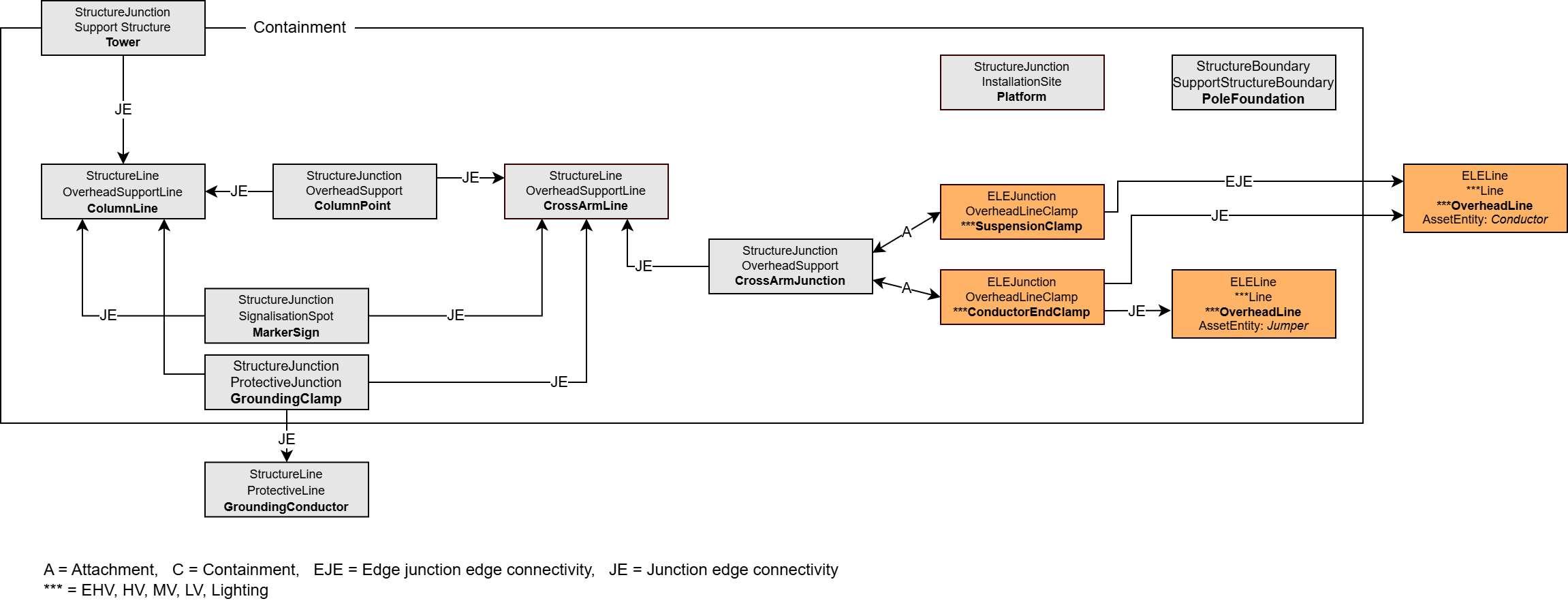
Structures without isolators can also be modeled. In that case, the relationships look like this:
|
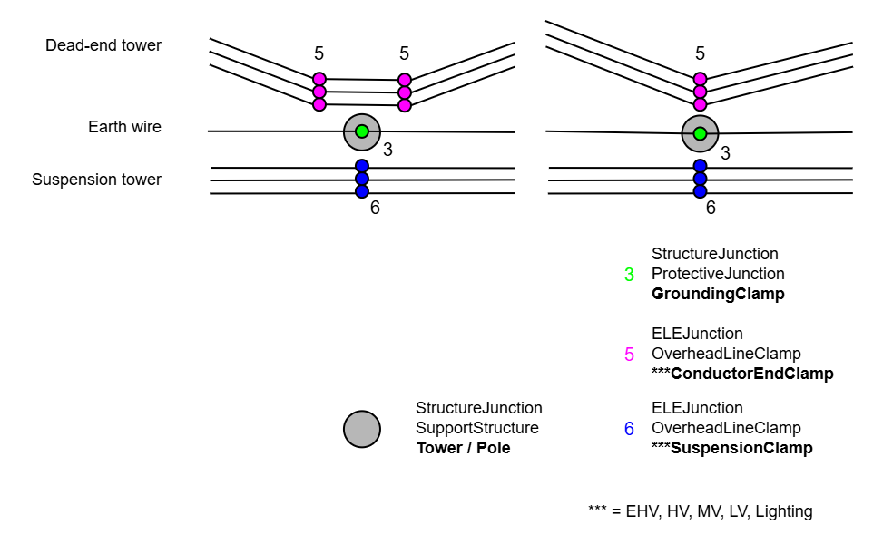
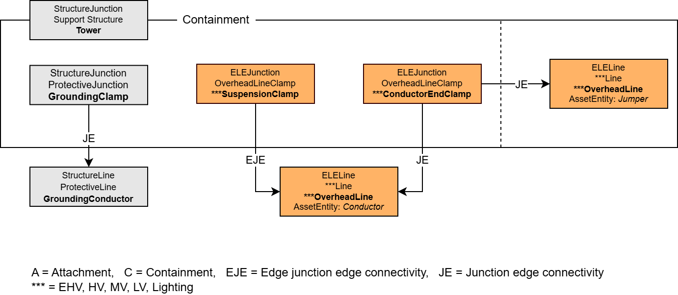
As the simplest case of structural modeling, it is sufficient to capture the structure's base point (StructureJunction:Support Structure:Tower or Pole). The suspension points of the cables are modeled at these points via Structural attachment associations. These are end clamps (ELEJunction:OverheadLineClamp:***EndClamp) for guyed masts, where the wires terminate at the insulator. On supporting masts, the wires are only suspended and not interrupted; the corresponding clamps are suspension clamps (ELEJunction:OverheadLineClamp:***SuspensionClamp). The ground wire is finally attached to the structure via a grounding clamp (StructureJunction:ProtectiveJunction:GroundingClamp). This clamp is placed directly at the structure's base point.
In this simple model, there are two options for modeling the transmission towers. Either with two clamps and a jumper in between (left illustration) or simplified with only one clamp (right illustration). The second case reduces the measurement effort, but the exact number of components and the total length of the conductor cables including the jumper can no longer be determined. The relationships between the objects are as follows:
The jumpers are optional. |
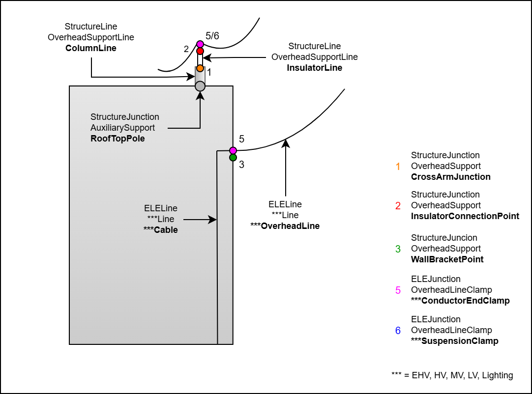
 RoofTopPole and WallBracketPoint
The modeling of a roof pole is carried out analogously to capturing a cantilever on a power line tower. A column line can be mounted on the StructureJunction RoofTopPole. The further construction corresponds to that of a tower.
|

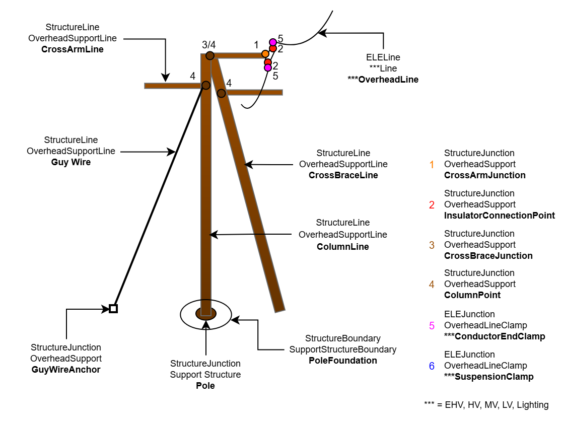
The modeling of the poles corresponds to that of the tower. Additionally, the support CrossBraceLine can be attached via a CrossArmJunction or a ColumnPoint. A guying can be implemented using the GuyWire, which is suspended on the structural side at the ColumnPoint and attached on the other side to the GuyWireAnchor. Complete capture in 3D:
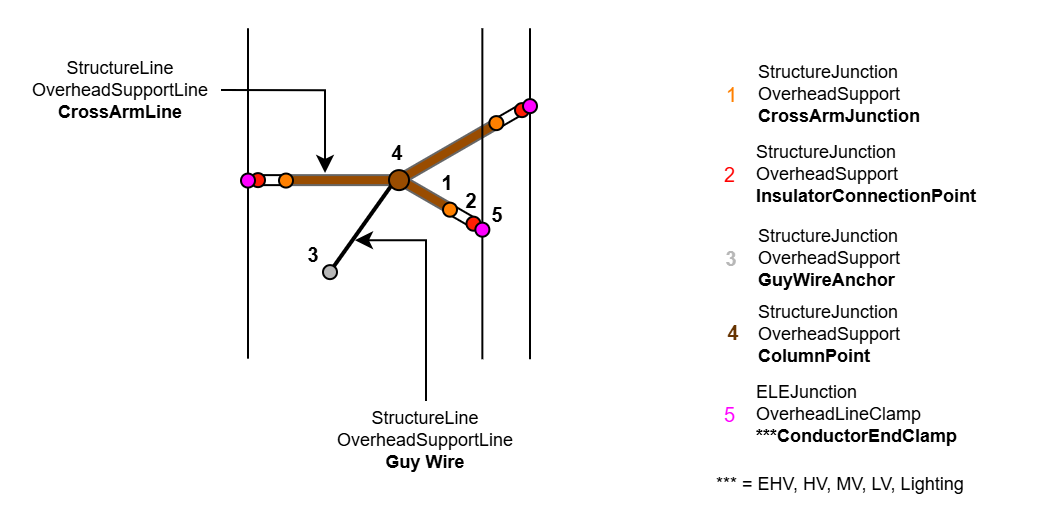
Complete capture in 2D:
Unlike the tower, additional supports can be installed on the pole. CrossBraceJunctions serve as support points, each with junction-edge connections to link with the ColumnLine on one side and the CrossBraceLine on the other. A guy wire can also be connected at the ColumnPoints for tensioning. The relationships between the objects are as follows:
|