The web-based user interface consists of different windows that can be freely configured in terms of their arrangement.
In the delivery state, the windows are arranged as shown in the picture below. Thus, it is only used to display and explain the individual window components and their designations.
An action menu belonging to a function is described according to the delivery status. If required, it can be configured individually via the App.JSON.
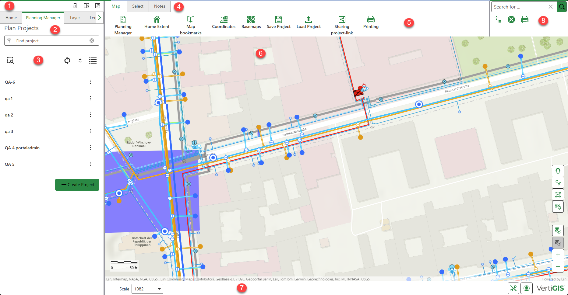

When the application is launched, the left side panel contains tabs that provide access to the following components:
In case you need more space, the left side panel can be minimized, maximized or undocked using the buttons in the upper right corner. |
||||||||||||||
The Planning Manager tab opens the Project window. Here projects can be created, edited, searched, sorted, highlighted in the map, updated and displayed with/without details. |
Already created projects appear in the sortable list of planning projects. |
The Map, Select, Notes and Edit tabs can be used to quickly access central components of theNetworks Simulator . Each of those tabs have their own toolbars Additional functions can be configured from VertiGIS Studio taking into account the licensing conditions.
|


Spatial information is visualized in the map window. Here you can navigate and use all available functions from the toolbar, so all layers in the project can be displayed, compared, analyzed, selected, evaluated, markups and notes that can be added. In addition to zooming via the plus/minus key or optionally with the mouse wheel, the following efficient navigation functions are available:
|
||||||||||||||||


The status bar can be configured as requested. In the solution, the following is displayed by default:
|


Frequently used functions are additionally offered in the upper right area for quick access. These are:
|


© 2026 VertiGIS Ltd. All Rights Reserved. | Privacy Center | Imprint
Documentation Version 1.18 (eb506704)