 Cathodic Corrosion Protection (CCP)
Corrosion is the destruction of metal through chemical or electrochemical reactions with the environment. Due to these reactions, potential differences occur between metallic materials and their conductive surroundings, leading to material loss on the surface. The potential difference as well as the conductivity of the medium determine the rate of corrosion.
Cathodic corrosion protection (CCP) is a method to protect metallic surfaces from corrosion. There are passive and active corrosion protection methods. In passive protection, the material is coated with a substance (resin, plastic, alloys). Active corrosion protection works with an electric circuit and uses either galvanic or impressed-current anodes. This chapter delivers editing guidelines for an active corrosion protection system.
Other electrical currents (stray currents) can also cause electrochemical corrosion. To prevent corrosion from stray currents, drainage cables can per example be used.
A measurement system system is used to test and adjust the CCP systems to ensure that continuous adequate protection is possible.
A CCP system can in reality be used across different domain networks. In the section on cross-domain CCP we describe how this can be supported in the network documentation.
| Impressed Current Anode |
|
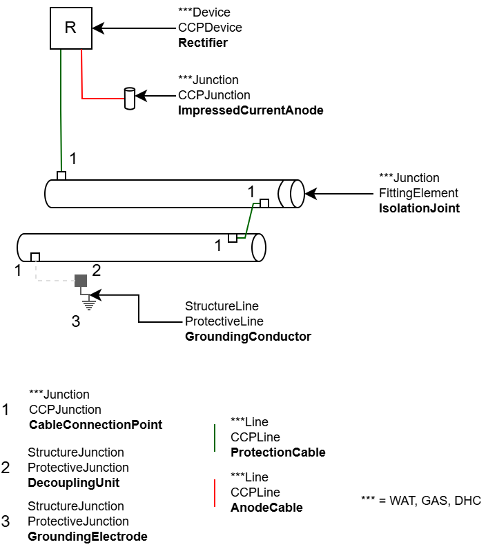
A Rectifier is the main element of the protective device of the CCP System system. The rectifier feeds the required protective current into the protected objects via impressed current anodes. It acts as a subnetwork controller: the subnetwork comprises the network elements protected by the rectifier.
An anode cable connects the impressed current anode(s) to the rectifier.
A cathode cable connects the rectifier (terminal "ToCathode") to the protected object. Several protected objects can be interconnected via a cathode cable, in order to extend the corrosion protection to different not topologically connected objects.
An insulating piece (IsolationJoint) can be used to interrupt the current, thereby limiting protection to a specific network area. Non-conductive pipe sections and fittings also stop the protective current. However, if the protective current is to pass over a non-conductive element, the non-conductive element can be bridged with cable. This bridging is recorded in the data model as an attribute (attribute CCP_Bonded), so that it is not necessary to record very small cable connections between pipes.
Pipes protected by the CCP are not connected directly to an earthing system, as the protective current would flow into the ground instead of protecting the pipe. The pipes can be connected to the ground via protective elements. These protective elements (DecouplingUnit, spark gaps) are only conductive in an emergency. They are installed in insulating sections or at stations with lightning protection requirements. Only in the event of a surge (lightning, etc.) is the current conducted to the ground to protect insulating sections and people.
Corrosion protection using external current offers several advantages. The protective current output can be easily regulated and adjusted to the resistance of the soil. Its protective effect has a long range. The material used in external current anodes ensures a longer service life.
However, the system has the disadvantage of requiring a larger investment, and external systems could also be affected.
|
|

|
In the galvanic system, anodes are sacrificed to protect the metal components. The anodes are generally made of magnesium, zinc, aluminum, and therefore have a potential that is favored by the corrosion processes. In this system, the sacrificial anode plays the role of the subnetwork controller.
A cathode cable (ProtectionCable) connects the sacrificial anode to the protected object. Several protected objects can be connected to each other via a cathode cable in order to extend protection to different not topologically connected objects.
Several anodes can be combined to form an anode field. If there is a need to document them individually, they can be recorded separately and grouped as an anode field using the “CCPAnodeGroup” assembly. The anodes can be connected to each other with an anode cable (Terminal "Rectifier_In").
An insulating piece (IsolationJoint) can be used to interrupt the current, thereby limiting protection to a specific network area. Non-conductive pipe sections and fittings also stop the protective current. However, if the protective current is to pass over a non-conductive element, the non-conductive element can be bridged with cable. This bridging is recorded in the data model as an attribute (attribute CCP_Bonded), so that it is not necessary to record very small cable connections between pipes.
Pipes protected by the CCP are not connected directly to an earthing system, as the protective current would flow into the ground instead of protecting the pipe. The pipes can be connected to the ground via protective elements. These protective elements (DecouplingUnit, spark gaps) are only conductive in an emergency. They are installed in insulating sections or at stations with lightning protection requirements. Only in the event of a surge (lightning, etc.) is the current conducted to the ground to protect insulating sections and people.
Installing a galvanic corrosion protection system is more cost-effective than installing an external current system. Maintenance costs are also lower. The current output is limited and the effect is more localized. However, the objects to be protected must be well insulated and the ground must be highly conductive.
|
|
| CCP Measuring System |
Measuring system
|
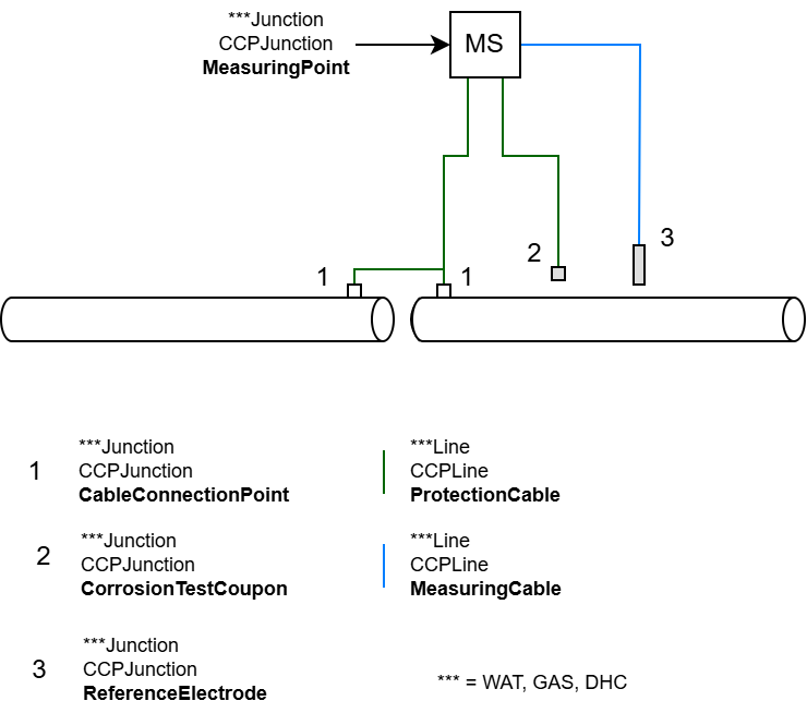
Permanent test stations are installed at selected locations along the protected structure to test, monitor, and control the performance of the cathodic protection. These measuring stations have different cable connections for connections to:
•one or more protected components
The cable is used to measure potential. The protective current from the anode flows through this cable (ProtectionCable) into the pipe.
•a continuous reference electrode (ReferenceElectrode)
The reference elctrode is optional, preferably installed in a measuring shaft. The electrode is used to measure the voltage between the pipe and ground potential. This checks whether the protection is sufficient. The cable is a measuring cable through which no protective current flows (MeasuringCable).
•A test coupon (CorrosionTestCoupon)
A small piece of metal that simulates the pipeline. This can be used to measure the effective protective current requirement and to better estimate the corrosion rate. For this reason, the test coupon absorbs the same protective current as the pipe. (connection with ProtectionCable)
•Bridging of an insulating piece
To check whether the resistance between both sides of the insulating piece is present and whether spark gaps are functioning correctly
•Track stray currents
For measuring wandering currents (see section on stray currents)
•The anode circuit
For determining the anode current and whether the anodes are working correctly (ProtectionCable)
Not all elements need to be present at all times. Which measuring cable is connected to which socket on the measuring station depends on the type of measurement to be made. A measuring station can have Earthing as lightning protection.
|
|
| CCP stray currents |
Streuströme bei Bahngleisen
|
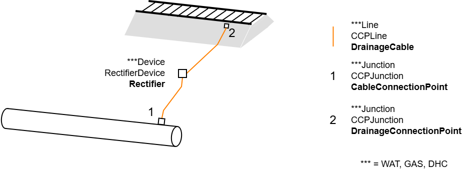
When metallic structures run parallel to railroad tracks, induced or stray currents are generated. In order to measure, monitor, and, if necessary, decouple these currents, a track return current system connects the track to a protected pipe.
The track return current system ensures that the DC current from the railway flows back through the rails in a controlled manner and not through the ground or close to metallic structures (e.g., pipes). It is a rectifier that converts the current into DC current. The rectifier is connected to the rails (return conductor) via a drainage cable. It feeds the return currents into the railway system via the cable.
|
|
| Multi-domain CCP |
Work with multi-domain network
|
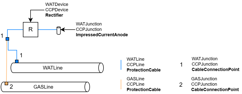
A CCP system can be used across different domain networks.
•If the domain networks are documented and managed separately, the CCP elements (rectifier, anode...) must be recorded in each domain.
• If several domains are managed in the same utility network in the GIS project, it is possible to define a cross-domain CCP system. The rectifier and the anodes must be recorded in a chosen domain network. The pipes are connected to the rectifier/anode via a ProtectionCable. The ProtectionCable connects to the pipes with CableConnectionPoints.
The CableConnectionPoints are the only multi-utility-capable objects. They can be placed on all other line objects and connected with a ProtectionCable. It is recommended to use KKS lines between devices and connection points from the same division as the devices, but this is not mandatory.
To enable valid topological connections between domains, specific topology rules must be imported, that are delivered separately to the Asset Package.
Cross-branch network tracing is possible.
Cross-branch subnetworks cannot be formed (esri technical limitation).
|
|
