Overview
Network > Cross Sections draws a cross-section of a structure line such as a trench: a grid showing which tubes and cables run through it, and where each one sits. Users can rearrange the grid, change symbols and place the drawing on the map.
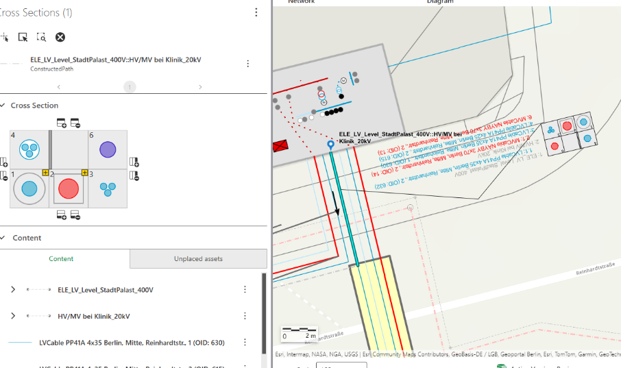
A network cross-section describes how equipment and content are arranged inside a structure line:
•The structure line acts as a container, and
•the cross-section is the blueprint of what's inside that container.
How Cross-Sections Are Built
A cross-section is built from two parts:
Part |
Stored as |
Holds |
|---|---|---|
Structure |
Utility network containment associations |
What is in the structure line: the trench contains tubes, tubes contain cables. |
Description |
A JSON file, attached as an Esri attachment to the structure line |
How it is drawn: grid size, cell positions, symbols, colours, placement on the map. |
Cross-sections are based on existing containment associations in the utility network. A cross-section does not independently define which cables or equipment belong to a structure line. It starts from the containment relationships already in place and adds layout information on top of them.
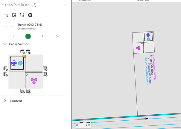
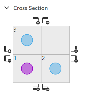
The cross-section description is stored as a JSON attachment on the structure line. This JSON holds the information needed to reconstruct the cross-section, such as the position and arrangement of each contained element. A cross-section is therefore not a separate GIS feature class or geometry layer. It is data attached to the structure line.
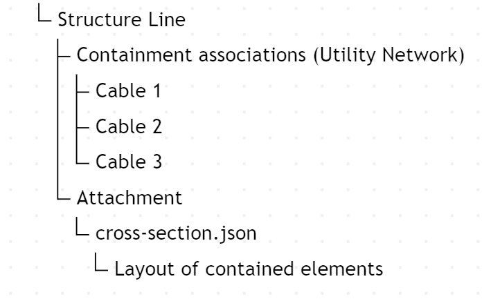
If no description is attached yet, Networks Editor generates the grid from the containment associations and marks it with a warning icon. Once a user saves a description, the attachment is the drawing.
Before You Begin
•The structure line hierarchy exists. At least one structure line (the trench, e.g. StructureLine) contains every line feature that runs through it, through containment associations. A container can hold tubes or lines, and a tube can hold further lines (see the hierarchy below).
•Attachments are enabled on the structure line class, so the description can be stored.
•The feature service has been republished since attachments were enabled.
Trench (StructureLine)
1:n containments - tubes or lines
1:n containments - lines
Only features with an association rule can be connected to each other through associations. The rules are part of the asset package / utility network configuration and are stored for each combination of FCL-AG-AT (feature class, asset group and asset type). For more information, see Edit Associations and the Esri help on Associations.
Setting Up Cross-Sections
1.Check the containment rules. The utility network rules must allow the structure line to contain the tubes and lines, and the tubes to contain the lines. If the rules do not allow the hierarchy, it cannot be created. The standard VertiGIS data models already have these rules. Check them in ArcGIS Pro: Utility network properties.
2.Check one structure line in ArcGIS Pro. Select a trench and confirm its content: the contained tubes and cables are listed as containment associations. If they are not, the app has nothing to draw.
3.Decide which structure line types support cross-sections. With no configuration, every structure line type supports them. To limit them to certain types, add the cross-sections-service configuration (see Configuration below).
4.Open a structure line in the app and check the generated grid. Save it with Save Cross Section Description to create the attachment.
5.If you migrate cross-sections from another system, write the description JSON yourself and attach it to each structure line (see The Description File below).
6.Move any app.json change into your custom solution package.
Once a description attachment exists, the grid is read from it, not from the containment associations. Changes in the panel are not kept until the user saves the description again. Reset cross section description goes back to the generated grid.
Configuration
The cross-sections-service configuration controls which structure line types support cross-sections in the Networks Editor web app. The web app can be configured through the app.json file which is accissible from the solutions package, the VertiGIS Studio Web Designer, or the Items Manager.
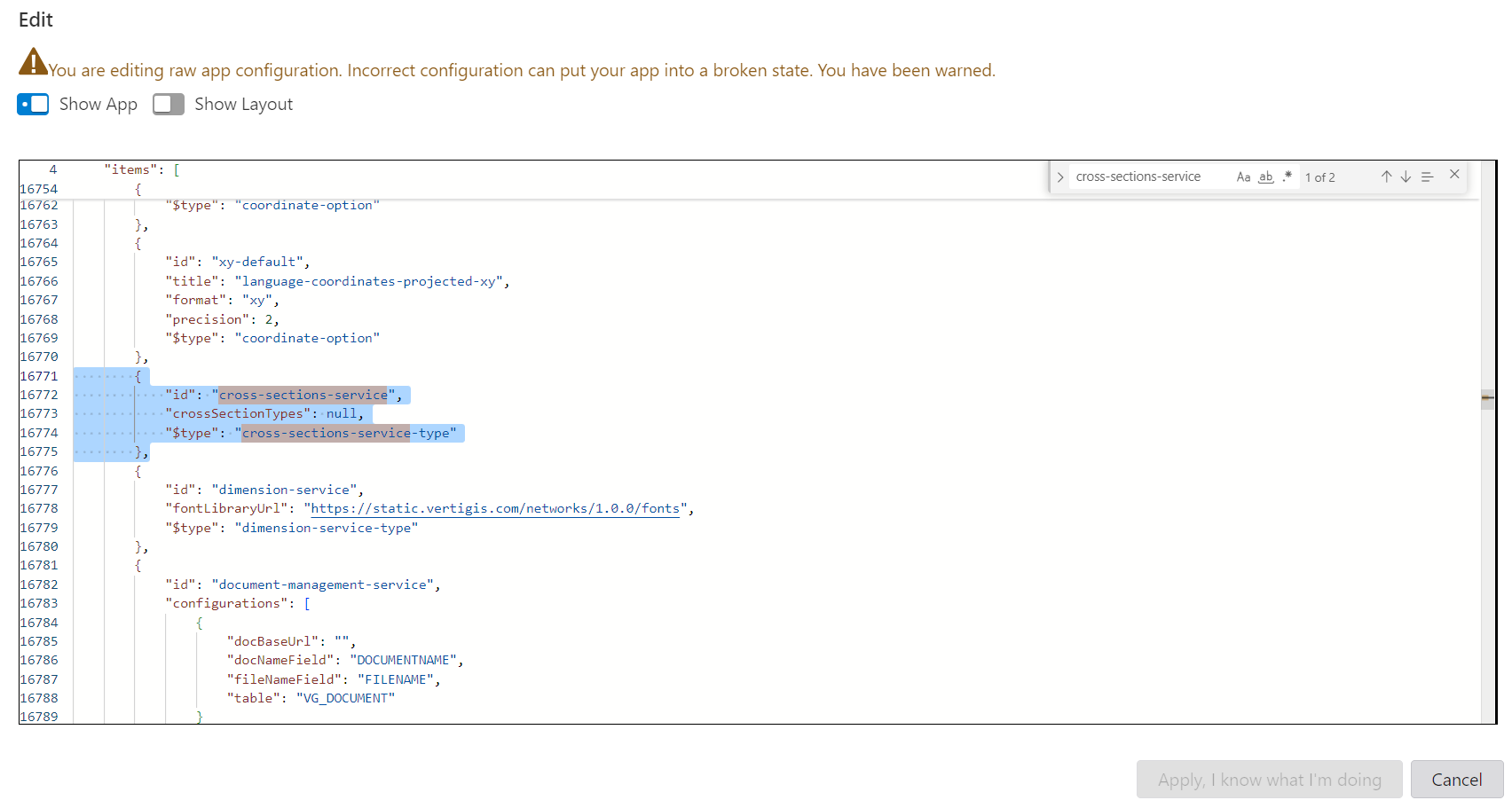
To access the json configuration (app.json) in VertiGIS Studio Web Designer, press Ctrl + Shift + E. Here's an example configuration:
{
"id": "cross-sections-service",
"crossSectionTypes": [
{
"assetGroup": 200,
"assetType": 202
},
{
"assetGroup": 200,
"assetType": 203
}
],
"$type": "cross-sections-service-type"
}
Table: properties and description of json configuration
Property |
Description |
|---|---|
id |
Identifier of the service. Must be cross-sections-service. |
$type |
Service type. Must be cross-sections-service-type. |
crossSectionTypes |
List of structure line types for which cross-sections are enabled. |
assetGroup |
Asset group code of the structure line type in the utility network. |
assetType |
Asset type code of the structure line type within that asset group. |
Each assetGroup and assetType pair identifies one structure line type in the utility network. Take the codes from the structure line's subtype and asset type domains, not from their descriptions. The example above enables cross-sections only for structure lines with asset group 200 / asset type 202 and asset group 200 / asset type 203.
If the cross-sections-service configuration is not present, all structure line types support cross-sections. Once the configuration is added, cross-sections are available only for the structure line types listed in crossSectionTypes. All other structure line types will not support cross-sections.
The Description File
The description is a JSON document attached to the structure line. You only need to know its structure when you generate descriptions during a data migration, or when you are diagnosing a drawing that looks wrong.
Elements
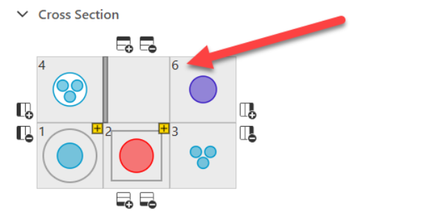
Each tube or cable in the grid is one element:
{
"refId": 13,
"className": "MVLine",
"globalId": "{ECF5E275-97B5-4B50-B595-33C678346614}",
"label": "MVCable NAYBY 3x70 Berlin, Mitte, Reinhardtstr., 2 (OID: 13)",
"autoPlacement": false,
"drawingIndex": 5,
"graphic": {
"type": "circle"
}
}
Table: properties of an element
Property |
Description |
|---|---|
refId |
The object ID of the feature. Networks Editor does not read it. If you have no object ID during migration, any number works. |
className |
The feature class of the tube or cable. |
globalId |
The global ID of the feature. This is how the element is matched to the feature. |
label |
The label shown next to the drawing. |
autoPlacement |
true for generated or migrated cross-sections. Becomes false once a user moves the element in the grid. |
drawingIndex |
The element's position in the grid, counted from the bottom-left cell starting at 0. The UI numbers cells from 1, so the cable shown in position 6 has drawingIndex 5. |
graphic.type |
The symbol: circle or rectangle (tubes), 3circle or 3x1circle (cables). |
Colour |
Optional. A colour a user sets is stored as RGB values on the element. |
Cells
cells sets borders on grid cells, for example cover stones. In most descriptions it is empty.
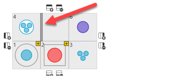
"cells": [
{
"drawingIndex": 4,
"graphic": {
"border": { "bottom": 0, "top": 0, "left": 6.4, "right": 0 }
}
}
]
Placement on the Map
placements stores where the drawing sits on the map and the line that connects it to the structure line:
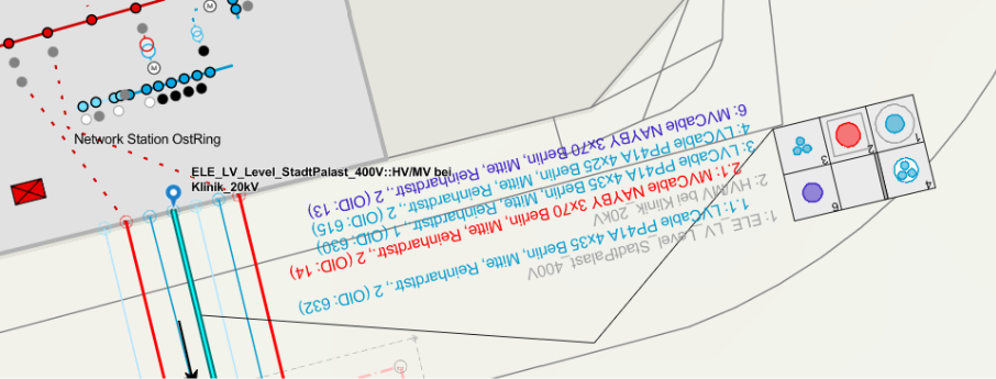
"placements": [
{
"centerX": 1490284.4580407972,
"centerY": 6895417.490601288,
"wkid": 102100,
"rotation": 193.5162154650194,
"scale": 1,
"referenceLine": [
{ "x": 1490261.7270350045, "y": 6895411.996619552 },
{ "x": 1490275.4603539129, "y": 6895411.05038547 },
{ "x": 1490281.637747017, "y": 6895418.526806274 }
]
}
]
Table: properties of a placement
Property |
Description |
|---|---|
centerX, centerY |
Centre of the drawing, in the coordinates of wkid. During migration you can fill it with the location of the cross-section. It is updated when a user moves the drawing. |
wkid |
Spatial reference of the coordinates, read from the web map. |
rotation |
Rotation of the drawing, in degrees. |
scale |
Scale factor of the drawing. |
referenceLine |
The leader line from the structure line to the drawing, as a polyline: an array of x/y vertices. |
viewdirection |
true draws the grid north-up relative to the map. false lets it flip with the viewing direction. |
The format allows layouts other than a grid, but only the grid is drawn at the moment.
See Also