Line
Lines always have a terminating element. It does not matter whether it is a device or a junction.
Description of Cases |
Graphic |
Examples Excerpt from the rules for the Utility Network |
|---|---|---|
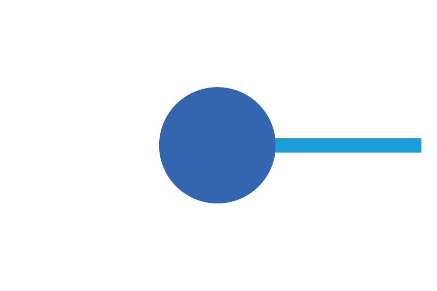
Consumer / ServiceConnectionDevice |
|
Consumers are found at the end of a line. Examples: •House connection •Hydrant •Gas lamp •etc. |
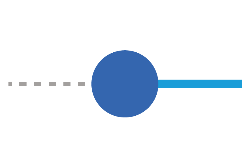
The special case InternalServiceLine allows additional consumers to be connected. |
|
Consumers can also connect additional consumers (including cascading) through an InternalServiceLine. |
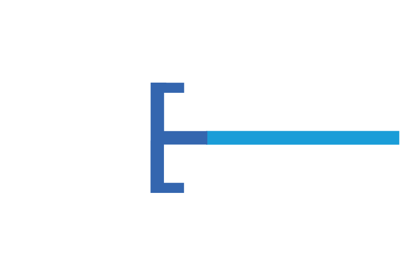
Junction |
|
The end of the line is sealed with a plug, blind flange, or cap (seeFittingElement). |
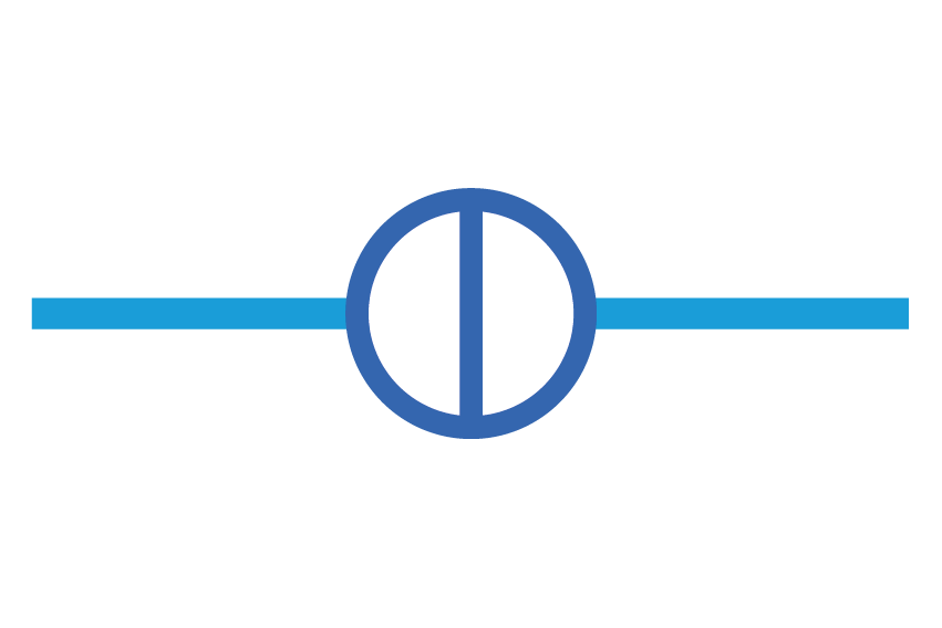
Schieber |
|
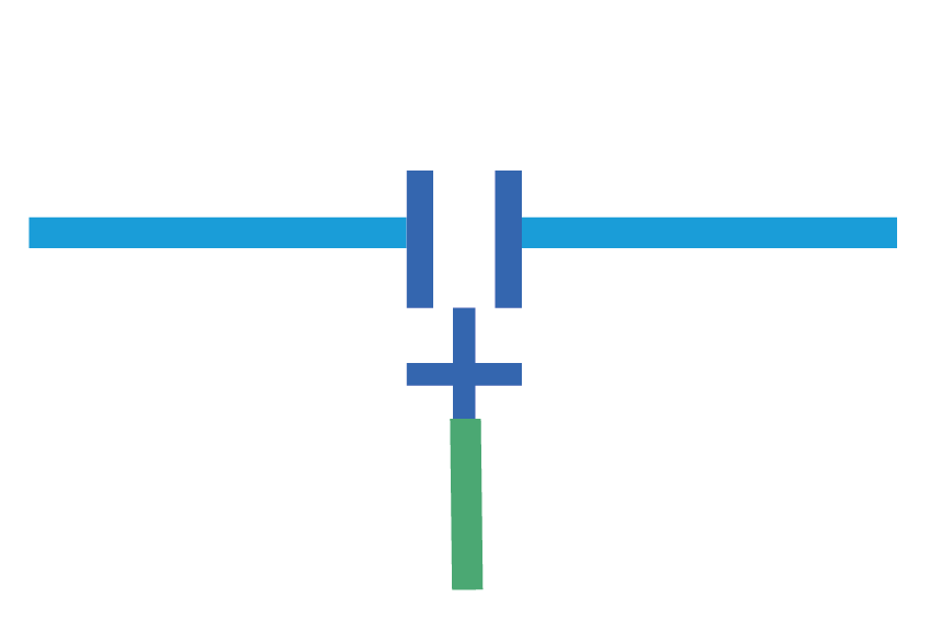
A valve is recorded between two lines. It can only be placed between two lines. |
|
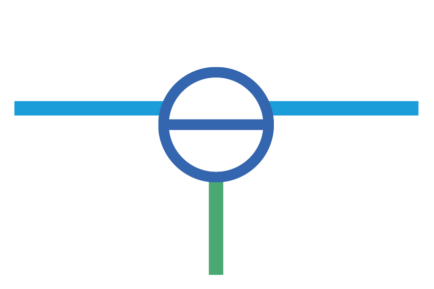
A tapping valve can be placed directly at an intermediate point on a line. It connects an uninterrupted line with a service line that can be controlled by the valve. |
|
Anbohrschieber mit versetztem Schiebersymbol |
|
|
|
|
|
Important Use Cases
Lines of the same level (asset group/asset type) can be directly connected without an intermediate or connector piece (device/junction). It should be noted that in the case of diameter or material changes, the corresponding junctions must be recorded (recommendation).
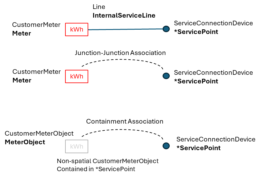
CustomerMeter (Device)
CustomerMeters can be managed both spatially and non-spatially. As objects with geometry, they can either be linked to the connection point via an internal service line or through a node-to-node relationship. In the case of the node-to-node relationship, the implicit connection can only be displayed as a line on the map through a specific function.
If the meter is not placed on the map, it can be associated with the connection point as an object via a "Containment Association".
Multiple CustomerMeters can be linked to a single connection point.
Junction
Currently, the detection of junctions is not of great importance for the network. As a rule, the same principles apply as for the devices. In addition, the junctions can also be connected on vertices or on lines. Other examples will be described in the future.
Assembly
The collection of assemblies is very much focused on the rules. Other examples will be described in the future.
Measuring Point and Measuring Devices:
Measuring devices are considered as SensorUnit (with geometry) or as SensorUnitObject (without geometry) are managed. They can be included in different assemblies (building, station, measuring point...). In order to locate the measuring devices via a network analysis, they must be directly integrated into the topological network:
- SensorUnit : located at the end or between lines
- SensorUnitObject: linked via a node-to-node relationship with a device or a junction in the network.
If multiple measuring devices need to be documented that are located in close proximity, a clearer representation of the geographical position can be achieved with the help of the measuring point (assembly SensorUnitGroup)The assembly is not directly part of the network, but marks the location of the assembly with a point symbol. It can contain 1 to n measuring devices.
Naming subnet controllers and subnetworks
Since the naming is individual, it will be described at a later stage.